Voltage reference circuit of pulse width modulation

A pulse width modulator and reference circuit technology, applied in the direction of adjusting electrical variables, instruments, electrical components, etc., can solve the problem of bandgap voltage output voltage Vo time difference and other issues

Inactive Publication Date: 2007-01-24
NANJING UNIV
View PDF0 Cites 20 Cited by
  • Summary
  • Abstract
  • Description
  • Claims
  • Application Information

AI Technical Summary

Problems solved by technology

[0012] The above is the reason for the overshoot phenomenon when the existing pulse width modulator system is just started. The most fundamental reason is that there is a time difference between the start-up of the bandgap voltage and the establishment of the output voltage Vo.

Method used


Image

  • Voltage reference circuit of pulse width modulation
  • Voltage reference circuit of pulse width modulation
  • Voltage reference circuit of pulse width modulation

Examples


Embodiment Construction

[0028] In order to have a further understanding of the structure and principle of the circuit of the present invention, a detailed introduction will be made below in conjunction with the accompanying drawings.

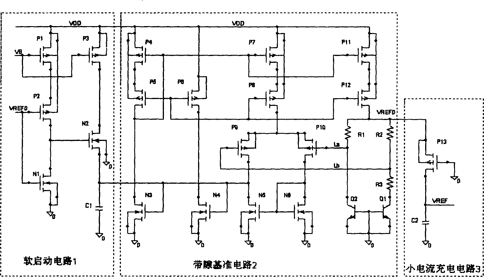
[0029] image 3 is an example of the bandgap reference circuit of the present invention. It includes soft start circuit 1, bandgap reference circuit 2 and small current charging circuit 3,

[0030] The bandgap reference circuit 2 is a common bandgap obtained through the principle of temperature compensation, and the power supply rejection ratio (PSRR) can be improved by adopting a cascode current mirror structure.

[0031] Soft-start circuit 1 is a simple and commonly used start-up circuit, which is composed of an inverter and an NMOS tube.

[0032] The small current charging circuit 3 is the core circuit for obtaining the slow start reference voltage. The width-to-length ratio of the PMOS transistor P13 is very small, the capacitor C2 is relatively large, and the c...


PUM


Abstract

This invention discloses a voltage primary circuit for a pulse width modulator including a soft start-up circuit, a band-gap primary circuit and a small current charge circuit, in which, the soft start up circuit provides suitable offset to the band-gap primary circuit to start it up smoothly, the output end of the primary signal VREFO is connected with the small current charge circuit, which uses the obtained small current to charge a rather big capacitor to rise the output signal VREF of the entire primary circuit steadily.

Description

1. Technical field [0001] The DC / DC pulse width modulator belongs to a class of power management chips, and the invention relates to a voltage reference circuit suitable for the pulse width modulator. 2. Background technology [0002] DC / DC pulse width modulators occupy a large proportion in power management chips, and are widely used in portable products, especially consumer electronics. [0003] figure 1 The basic circuit structure of a commonly used pulse width modulator (PWM) is given, which consists of error amplifier, startup circuit and reference circuit, phase compensation, pulse width modulation controller, comparator, ramp generator and oscillator, buffer drive These modules are composed, and the reference voltage module is a common bandgap reference circuit. [0004] figure 2 It is an architecture diagram of a step-up DC / DC converter based on the principle of pulse width modulation, and the chip part is figure 1 content shown. [0005] Let's take the step-up...

Claims


Application Information

Patent Timeline
Patent Type & Authority Applications(China)
IPC IPC(8): H02M3/155H02M3/156H02M1/08G05F1/46
Inventor 高明伦郎君何书专陈思远李丽李伟杨盛光
Owner NANJING UNIV
Why Eureka
Try Eureka