
Multiple air-intaking channel and supersonic speed whirl-flow separator and its back pressure device

A swirl separation, supersonic technology, applied in swirl devices, devices whose axial direction of swirl remains unchanged, separation methods, etc. question

Inactive Publication Date: 2007-01-31
XI AN JIAOTONG UNIV
View PDF7 Cites 33 Cited by
  • Summary
  • Abstract
  • Description
  • Claims
  • Application Information

AI Technical Summary

Problems solved by technology

However, the part that generates swirl in this device is a slender delta wing with a large sweep angle. Although it has the advantage of high swirl separation efficiency, it is also the weakest component in the device, which reduces the inherent safety of the device and reduces the service life. The main factors that reduce the total pressure efficiency

Method used


Image

  • Multiple air-intaking channel and supersonic speed whirl-flow separator and its back pressure device
  • Multiple air-intaking channel and supersonic speed whirl-flow separator and its back pressure device
  • Multiple air-intaking channel and supersonic speed whirl-flow separator and its back pressure device

Examples


Embodiment Construction

[0013] The structural principle and working principle of the present invention will be further described in detail below in conjunction with the accompanying drawings.

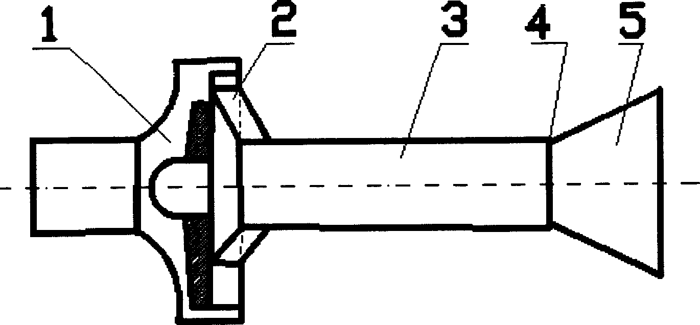
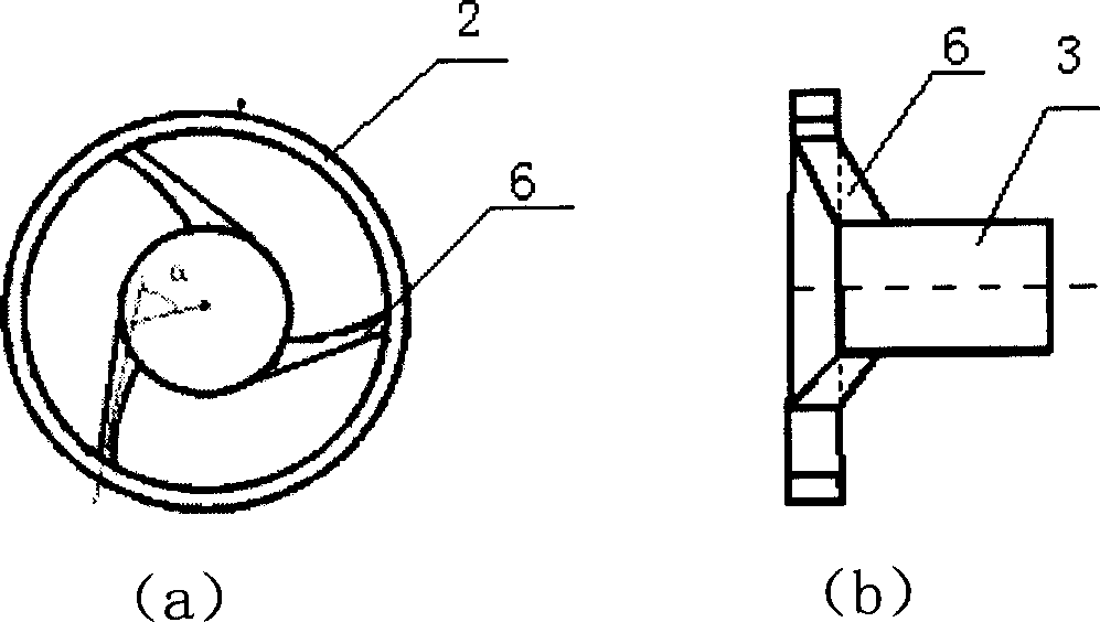
[0014] see figure 1 , the present invention comprises diversion chamber 1 and the nozzle pipe 2 that communicates with diversion chamber 1 and cyclone separation section 3, the outlet of cyclone separation section 3 is communicated with back pressure device 5, and the outlet between cyclone separation section 3 and return A liquid discharge port 4 is also arranged between the compressors 5, because the device works in a high-pressure and corrosive environment, so the material of the device is required to be resistant to high pressure, corrosion and erosion.

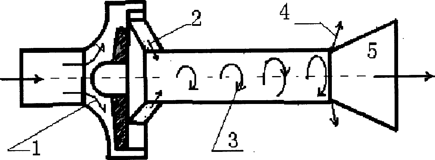
[0015] see figure 2 , the working principle of the present invention is as follows: the moisture is rectified in the diversion cavity 1 and the flow direction is changed to ensure that the high-pressure airflow enters the nozzle 2 along the circumferenc...


PUM


Abstract

A supersonic cyclone separation and pressure return mechanism with multiple air inlet channels is composed of flow guide cavity, jet tube, cyclone separation segment, pressure returning unit, annular liquid discharging outlets between cyclone separation segment and pressure returning unit, and a locator on said pressure returning unit for regulating the gap between liquid discharging outlets.

Description

technical field [0001] The invention relates to a wet natural gas separation system, in particular to a multi-inlet supersonic cyclone separation and backpressure device for removing harmful components (water vapor, C4, C5, etc.) in natural gas that are not conducive to long-distance pipeline transportation . Background technique [0002] In the development of land and offshore gas fields in my country, how to achieve efficient and economical dehydration of natural gas, and meet the requirements of environmental protection, so that the dew point temperature of water in natural gas can be reduced to 5-15 °C below the minimum ambient temperature along the gas pipeline to avoid the formation of Major accidents of pipeline blockage caused by hydrates, and at the same time reducing the content of heavy hydrocarbons and other components in natural gas to the range required by the process flow, are major issues that need to be solved urgently in natural gas production. [0003] At ...

Claims


Application Information

Patent Timeline
IPC IPC(8): B04C3/00B04C3/06B01D51/08B01D45/16E21B43/38
Inventor 白博峰苏燕兵严俊杰王俊奇
Owner XI AN JIAOTONG UNIV
Learn More