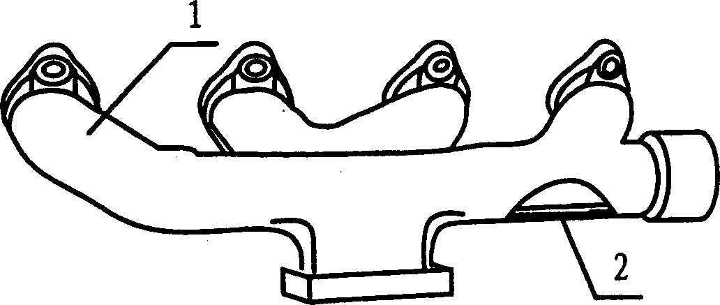
Cast iron exhaust branch pipe having oxidized layer on surface and its surface oxidation method
A technology for exhaust manifolds and oxide layers, which is applied to exhaust devices, coatings, solid-state diffusion coatings, etc., and can solve the problems of poor appearance quality, easy rust and corrosion on the outer wall of the exhaust manifold, and poor wear resistance of the joint surface And other problems, to achieve good wear resistance and stability, improve appearance quality, improve the effect of sealing
- Summary
- Abstract
- Description
- Claims
- Application Information
AI Technical Summary
Problems solved by technology
Method used
Image

Examples
Embodiment 1
[0021] 1) Clean the cast iron exhaust manifold;
[0022] 2) Install the workpiece in the fixture, and put the fixture with the workpiece into the steam oxidation treatment furnace at room temperature;
[0023] 3) Set the furnace temperature instrument at 300°C, turn on the power to raise the temperature, and open the nitrogen valve to feed in nitrogen while the temperature is rising. The speed of nitrogen feeding is 16m 3 / h;
[0024] 4) After the furnace temperature reaches the set temperature of 300°C, keep it warm for 1.5 hours. While keeping warm, nitrogen gas is introduced at a speed of 16m 3 / h;
[0025] 5) Set the furnace temperature instrument at 630°C, continue to heat up while maintaining the nitrogen gas flow, turn off the nitrogen gas when the temperature reaches the set temperature, and pass in water vapor, the speed of water vapor is 5±1m 3 / h (the measurement error of water vapor is ±1m 3 / h);
[0026] 6) Keep the furnace temperature at the set temperature ...
Embodiment 2
[0029] 1) Clean the cast iron exhaust manifold;
[0030] 2) Install the workpiece in the fixture, and put the fixture with the workpiece into the steam oxidation treatment furnace at room temperature;
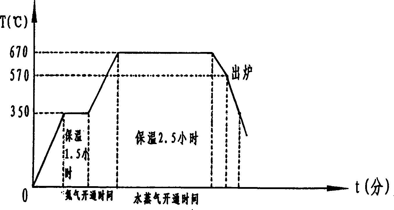
[0031] 3) Set the furnace temperature instrument at 350°C, turn on the power supply to raise the temperature, and open the nitrogen valve to feed nitrogen gas while heating up, and the nitrogen gas feeding speed is 18m3 / h;
[0032] 4) After the furnace temperature reaches the set temperature of 350°C, it is kept for 1.5 hours, and nitrogen gas is introduced at the same time as the temperature is kept at a rate of 18m3 / h;
[0033] 5) Set the furnace temperature instrument at 670°C, continue to raise the temperature while maintaining the nitrogen gas flow, turn off the nitrogen gas when the temperature reaches the set temperature of 670°C, and let water vapor flow in at a speed of 5±1m3 / h ( The measurement error of water vapor is ±1m3 / h);
[0034] 6) Keep the furnace temperatur...
Embodiment 3
[0037] 1) Clean the cast iron exhaust manifold;
[0038] 2) Install the workpiece in the fixture, and put the fixture with the workpiece into the steam oxidation treatment furnace at room temperature;
[0039] 3) Set the furnace temperature instrument at 420°C, turn on the power supply to raise the temperature, and open the nitrogen valve to feed nitrogen gas while heating up, and the nitrogen gas feeding speed is 20m3 / h;
[0040] 4) After the furnace temperature reaches the set temperature of 420°C, it is kept for 1.5 hours, and nitrogen gas is introduced at the same time as the temperature is kept at a rate of 20m3 / h;
[0041] 5) Set the furnace temperature instrument at 690°C, continue to raise the temperature while maintaining the nitrogen gas flow, turn off the nitrogen gas when the temperature reaches the set temperature of 690°C, and let water vapor flow in at a speed of 5±1m3 / h (the measurement error of water vapor is ±1m3 / h);
[0042] 6) Keep the furnace temperatur...
PUM
| Property | Measurement | Unit |
|---|---|---|
| thickness | aaaaa | aaaaa |
Abstract
Description
Claims
Application Information
 - R&D
- Intellectual Property
- Life Sciences
- Materials
- Tech Scout
- Unparalleled Data Quality
- Higher Quality Content
- 60% Fewer Hallucinations
Browse by: Latest US Patents, China's latest patents, Technical Efficacy Thesaurus, Application Domain, Technology Topic, Popular Technical Reports.
© 2025 PatSnap. All rights reserved.Legal|Privacy policy|Modern Slavery Act Transparency Statement|Sitemap|About US| Contact US: help@patsnap.com