Ion beam apparatus

一种离子束、质量分离的技术,应用在放电管、电气元件、电路等方向,能够解决束流线长度增加等问题

Inactive Publication Date: 2007-01-31
NISSIN ION EQUIP CO LTD
View PDF5 Cites 41 Cited by
  • Summary
  • Abstract
  • Description
  • Claims
  • Application Information

AI Technical Summary

Problems solved by technology

In any case, there is still the problem of increased beamline length

Method used


Image

  • Ion beam apparatus
  • Ion beam apparatus
  • Ion beam apparatus

Examples


Embodiment Construction

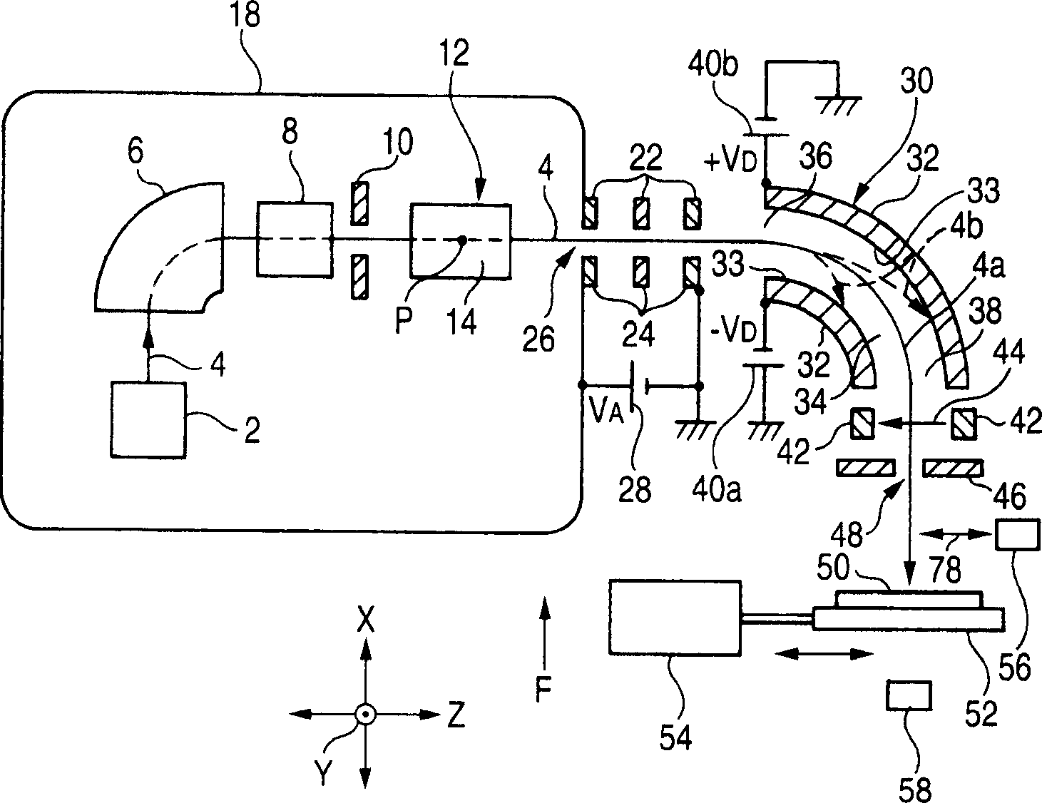
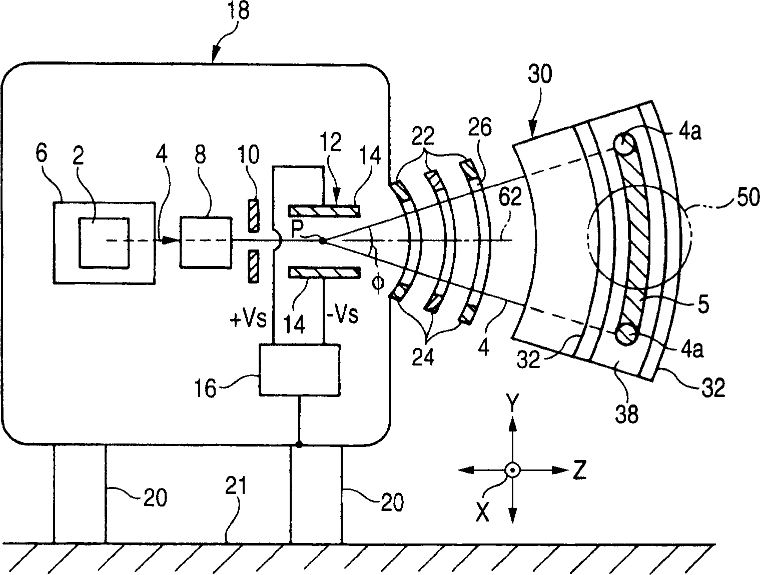
[0111] figure 1 is a plan view showing an embodiment of an ion beam apparatus (specifically, an ion implantation apparatus) according to the present invention. figure 2 is viewed in the direction of arrow F, partly shown figure 1 Front view of the ion beam assembly shown, showing a portion of the ion beam assembly from the ion source to the electrostatic deflector exit. In the following description, in the region along the path of propagation of the ion beam 4 extracted from the ion source 2, the region near the ion source is referred to as an "upstream region", and the opposite region is referred to as a "downstream region".

[0112]The ion beam device includes an ion source 2 that extracts an ion beam 4; a mass separation electromagnet 6 that separates an ion beam 4 of a desired mass (that is, performs mass separation of the ion beam 4 ) from the ion beam 4 extracted by the ion source 2 ; and with a given scan center P as the center, on a given scan surface 13 (see im...


PUM


Abstract

An ion beam apparatus comprises an ion source 2 which extracts an ion beam 4, a mass separation electromagnet 6 which separates an ion beam 4 of desired mass from the ion beam 4 extracted from the ion source, a scanner 12 which scans the injected ion beam 4 with a given scan center as center within a given scan surface, an electrostatic deflector which deflects the ion beam through 90 DEG so that an ion beam of desired energy in said ion beam travels in a direction perpendicular to said scan surface within a circular-arc-shaped deflection zone centered on the scan center, and a scanning mechanism 54 which retains a target 50 and which mechanically, reciprocally moves the target 54 in a direction in which the target crosses the ion beam passed from the electrostatic deflector 30 at a given angle.

Description

technical field [0001] The present invention relates to an ion implantation apparatus for performing ion implantation by irradiating an ion beam onto a target, and to an ion beam constituting the ion implantation apparatus and including an ion beam deflector for scanning and deflecting an ion beam device. Specifically, the present invention relates to an ion beam device capable of shortening the length of an ion beam streamline. Background technique [0002] In ion beam devices (hereinafter, ion implantation devices are exemplified) such as ion implantation devices, ion beam parallelism has hitherto been achieved so that the incident angles of ion beams within a target plane (eg, semiconductor substrate) are uniform. [0003] In order to prevent ions of undesired energy (called "energy contamination" or "energy contamination") from being injected into the target with the required energy (this injection is called "energy contamination" or "energy contamination"), Ions of un...

Claims


Application Information

Patent Timeline
Patent Type & Authority Applications(China)
IPC IPC(8): H01J37/317H01J37/05H01J37/147
CPCH01J37/05H01J2237/057H01J2237/053H01J37/3171H01J37/1477
Inventor 内藤胜男藤田秀树
Owner NISSIN ION EQUIP CO LTD
Why Eureka
Try Eureka