Reciprocating pump device

A technology for reciprocating pumps and input shafts, which is applied to variable displacement pump components, components of pumping devices for elastic fluids, pump components, etc. It can solve the problems of large bending stress of the crankshaft and long distance between crankshaft bearings, etc., and achieve Reduced bending stress, improved reliability, and improved durability

Inactive Publication Date: 2007-02-07
MARUYAMA MFG CO INC
View PDF0 Cites 23 Cited by
  • Summary
  • Abstract
  • Description
  • Claims
  • Application Information

AI Technical Summary

Problems solved by technology

However, in such a reciprocating pump device, since the crankshaft has a long distance between bearings, it is generally considered that a large bending stress may be generated on the crankshaft

Method used


Image

  • Reciprocating pump device
  • Reciprocating pump device
  • Reciprocating pump device

Examples


Embodiment Construction

[0015] Next, preferred embodiments of the reciprocating pump device of the present invention will be described in detail.

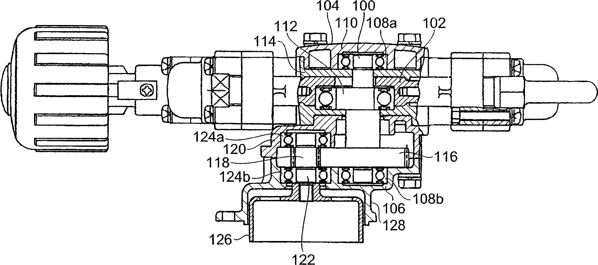
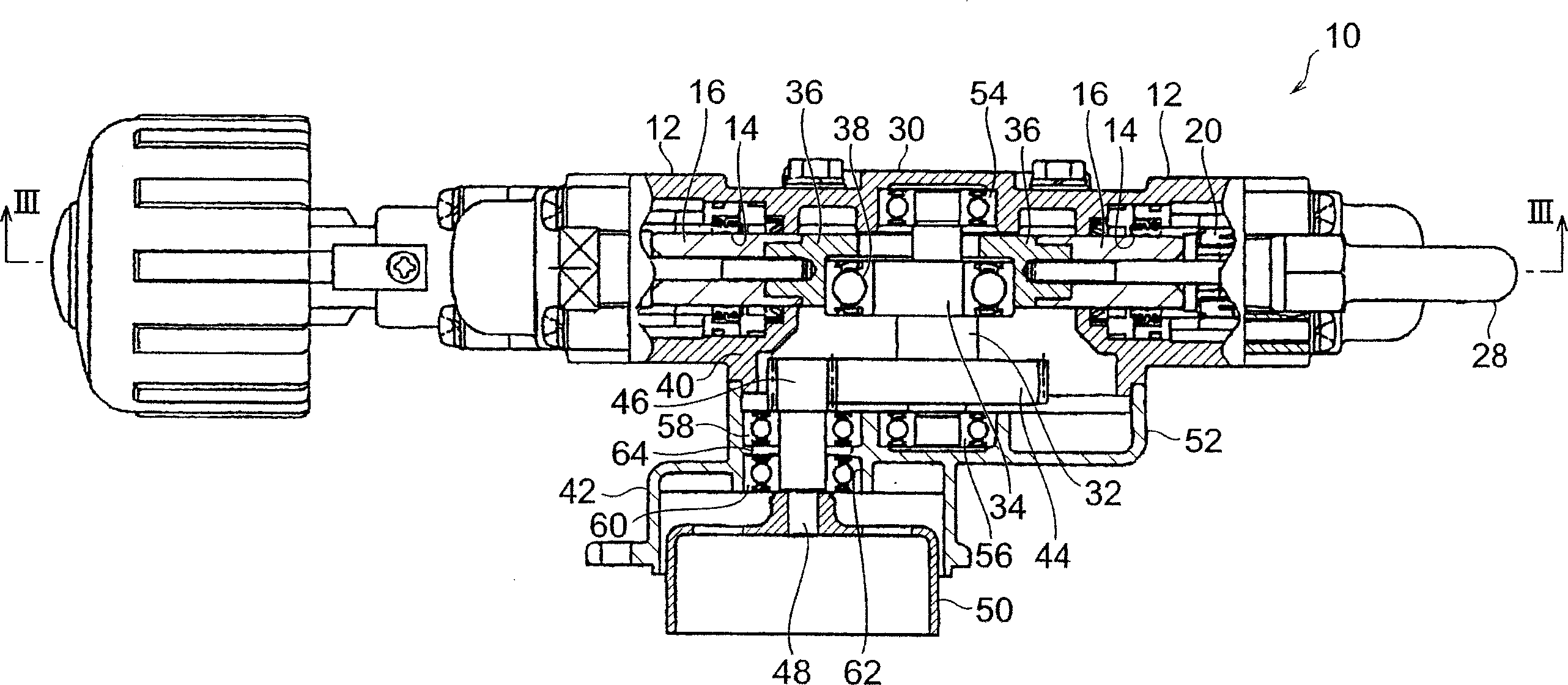
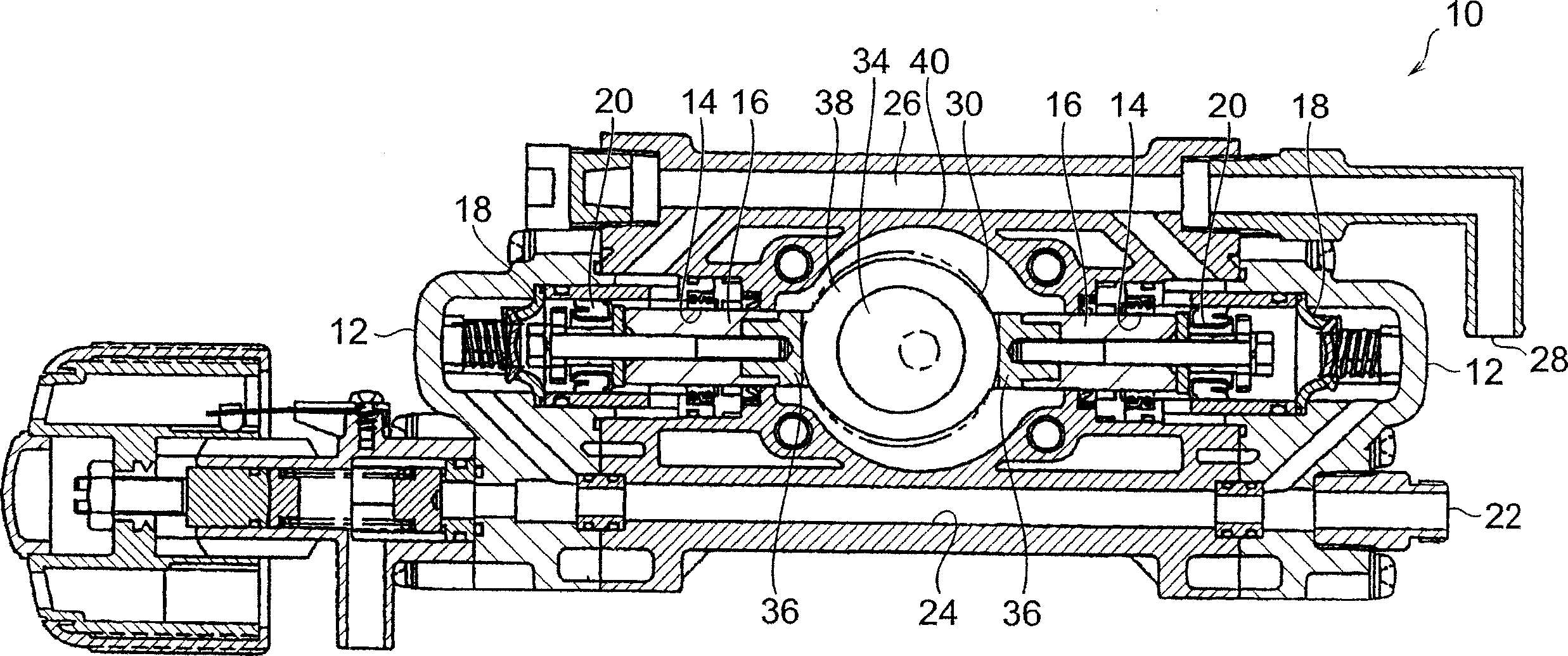
[0016] figure 2 is a partial sectional view of the reciprocating pump device of the present invention, image 3 is along figure 2 Partial sectional view of line III-III in. In the illustrated reciprocating pump device 10 , two reciprocating pumps 12 are arranged in a row in a state facing each other. Each reciprocating pump 12 includes: a hydraulic cylinder 14, a piston 16 reciprocating in the hydraulic cylinder 14, a discharge valve 18, and a suction valve 20; wherein, through the reciprocating movement of the piston 16, the liquid passes through the flow path 24 from the suction port 22, And flow through the flow path 26 and be discharged from the drain port 28 . Since the reciprocating pumps 12 operate alternately, the liquid is continuously supplied to the flow path 26 , so that the liquid is efficiently and stably discharged from the drain port...


PUM


Abstract

The invention provides a reciprocating pump device capable of reducing bending stress acting on a crank shaft. In the reciprocating pump device (10) provided with a drive part (30) including a crank shaft driving a piston (14) of a reciprocating pump (12) and a reduction gear part (42) arranged with adjoining the drive part and including a large gear (44) attached on the crank shaft and a small gear (46) meshing with the large gear and attached to the input shaft (48) to which power is input, a first bearing (58) and a second bearing (56) rotatably supporting the input shaft are collected on a side opposite to the drive part (30) and the input shaft (48) is supported in a cantilever style. Consequently, the small gear is put close to the drive part and total length of the crank shaft is shortened to reduce bending stress.

Description

technical field [0001] The present invention relates to a reciprocating pump, in particular to the structure of a driving part and a decelerating part of a reciprocating pump device. Background technique [0002] There are many known reciprocating pump devices, and Japanese Utility Model Invention Registration No. 2545985 discloses a reciprocating pump device used in knapsack power sprayers and the like. Such as figure 1 As shown, in order to achieve miniaturization, the reciprocating pump has integrally a driving part 104 for making the piston reciprocate in the cylinder and composed of a crankshaft 100 and a connecting rod 102, and a power of an engine (not shown) It is decelerated and transmitted to the deceleration unit 106 of the drive unit 104 . [0003] The driving part 104 and the decelerating part 106 are accommodated in the housing, and the housing is composed of the following parts: a bearing housing 110 for fixing 108a of the bearings 108a, 108b supporting the ...

Claims


Application Information

Patent Timeline
Patent Type & Authority Applications(China)
IPC IPC(8): F04B53/00
Inventor 谏山和博
Owner MARUYAMA MFG CO INC
Why Eureka
Try Eureka