Screwdriver device and screw

A screw and screw head technology, applied in the direction of screws, nuts, bolts, etc., can solve problems such as difficulty in obtaining fastening force, damage to the appearance of mechanical products, and loose screws

Active Publication Date: 2007-02-07
NIPPON TELEGRAPH & TELEPHONE CORP
View PDF4 Cites 18 Cited by
  • Summary
  • Abstract
  • Description
  • Claims
  • Application Information

AI Technical Summary

Problems solved by technology

In addition, when the number of screws to be fastened is large, or the parts for fastening the screws are hard, etc., very large physical strength is required, or a very large load such as electric power is required.
[0009] On the other hand, there are problems such as the following in mechanical products and the like constituting exterior structural parts by screwing: since the top of the screw head is naturally exposed on the surface, it may be damaged due to the concave marking or setting provided on the top of the screw head. Fastening mechanisms such as claws on the peripheral side seriously damage the overall appearance of the mechanical product
[0010] Furthermore, for screws fastened to structural parts (parts to be fastened), if there is a screw driving device whose end shape corresponds to the fastening mechanism, it can be easily loosened. It is extremely inappropriate if the screw tightened in the normal process is loosened by a third party, and there will be a problem (for example, when the product guarantee condition is that no screw loosening operation has been performed)
[0011] Furthermore, there is also the following problem: if the mechanical product constructed by screw joint is used for a long time, the screw will loosen naturally
[0014] However, when tightening a screw simply by pressing a piezoelectric screwdriver against the top of the screw without markings, it may be difficult to obtain a sufficiently high tightening force, and a higher tightening force is required for reliable screw tightening.

Method used


Image

  • Screwdriver device and screw
  • Screwdriver device and screw
  • Screwdriver device and screw

Examples


no. 1 Embodiment approach

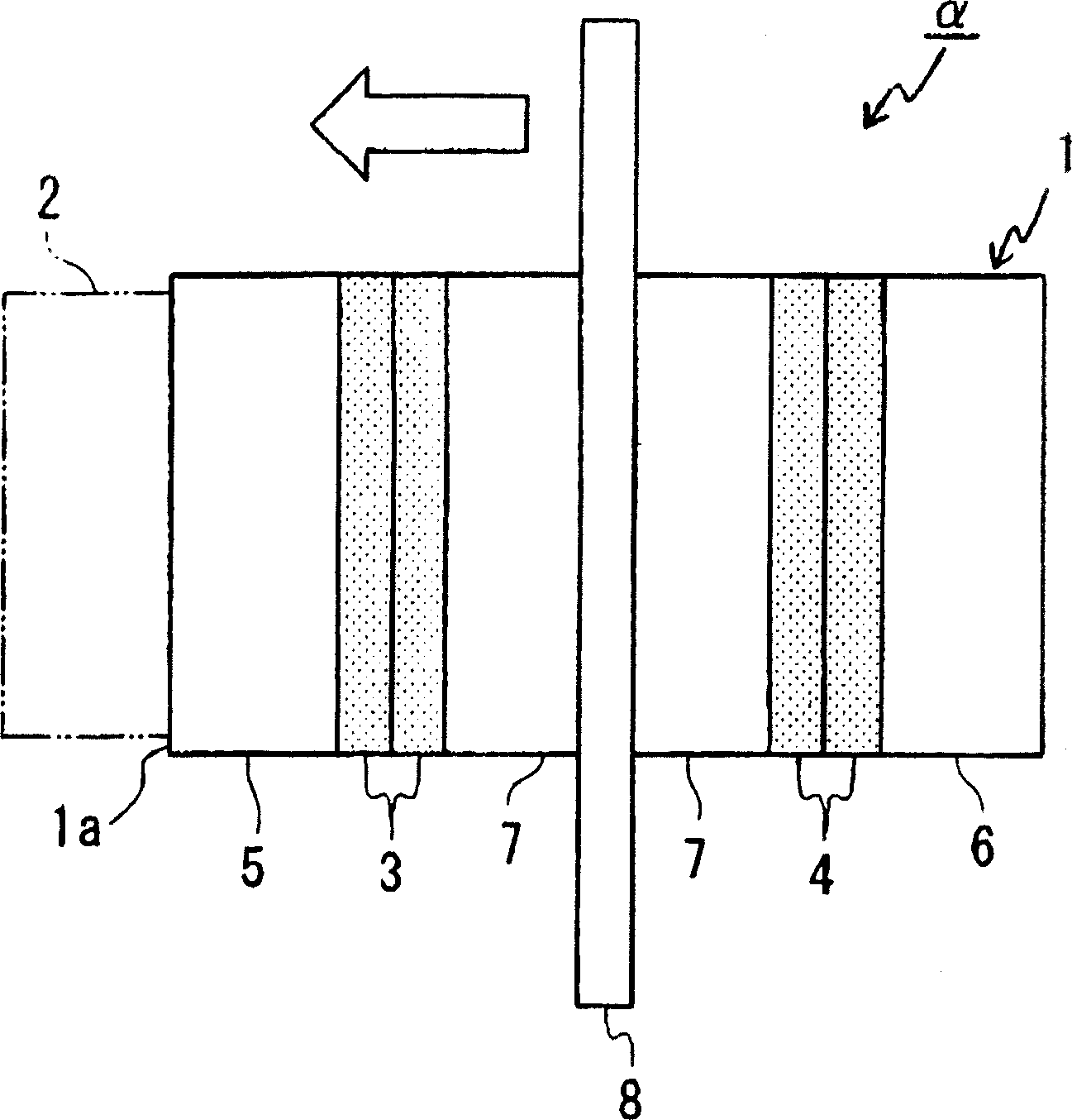
[0192] First, as the first embodiment, using figure 1 The basic idea of ​​the screw driving device of the present invention will be described. The screw turning device α is used to fasten or loosen the screw relative to the corresponding threaded hole formed on any part to be fastened. It has a device main body 1 and an Vibration-transmitting mechanism 2 for contact.

[0193] The device main body 1 is composed of a plurality of piezoelectric elements 3, 4 that generate flexural vibration in two directions perpendicular to each other, an end vibrating member 5 and a rear end vibrating member 6, two central vibrating members 7, 7, and The flange members 8 are stacked and fastened with bolts (not shown).

[0194] A predetermined AC voltage is applied from an AC power source (not shown) to a plurality of piezoelectric elements 3, 4..., and ultrasonic vibrations are generated thereupon. (i.e., screws ( figure 1 Not shown in the figure)) performs a rotational movement around an ...

no. 2 Embodiment approach

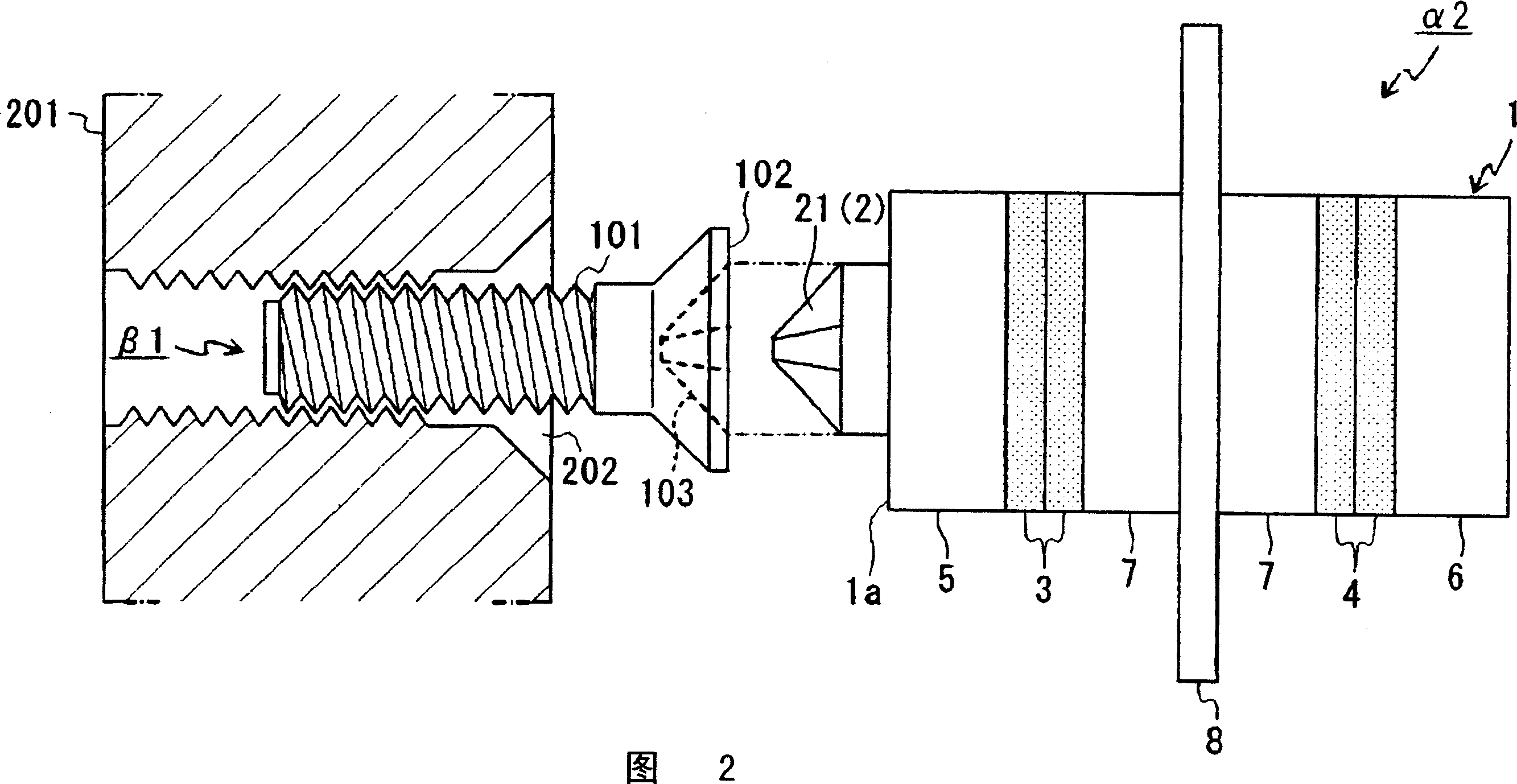
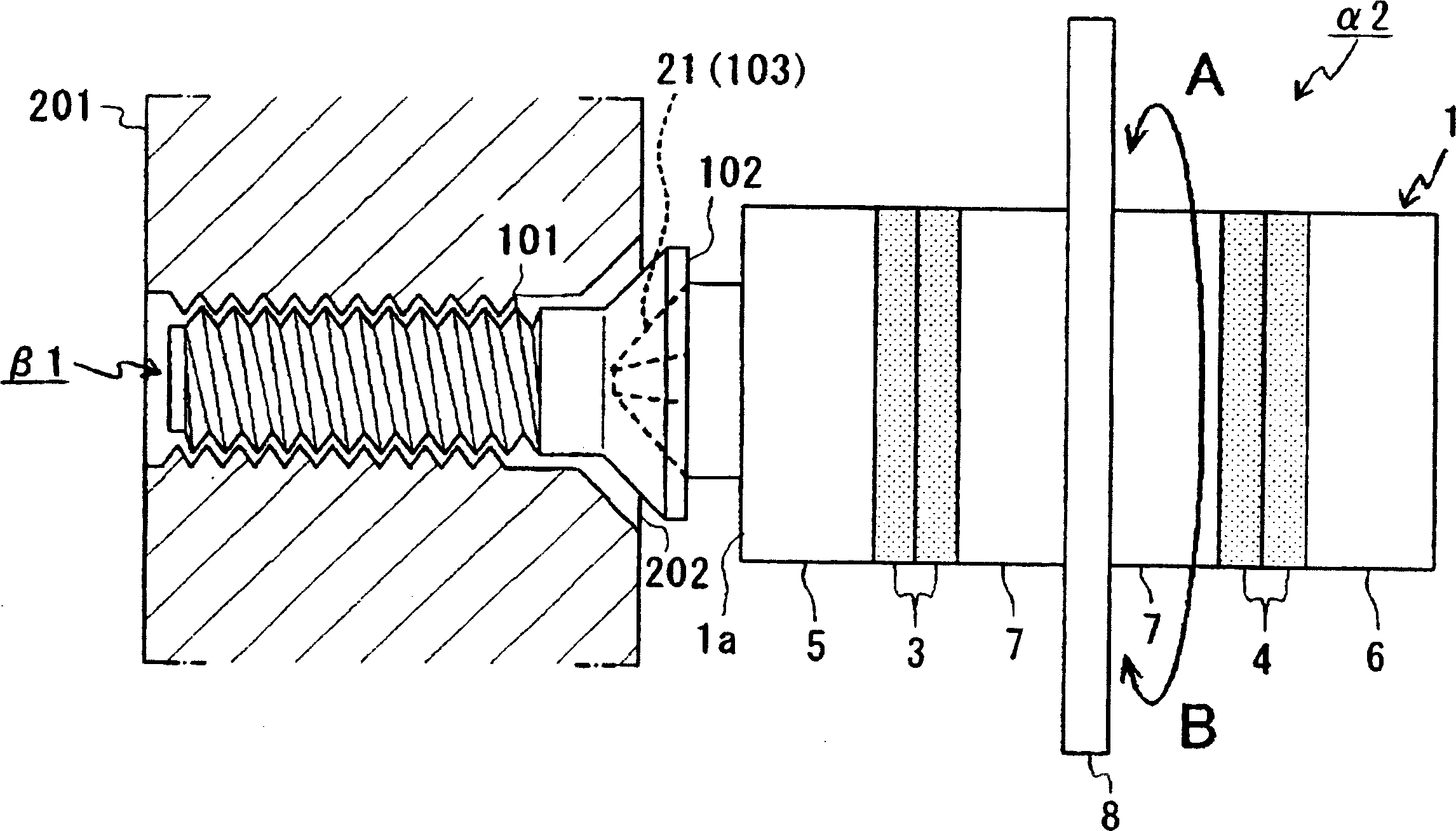
[0206] Next, as a second embodiment of the present invention, using FIG. 2 and image 3 , an application example of the screw driving device described in the above-mentioned embodiment will be described.

[0207] This screw driving device α2 is an example that has, as the above-mentioned vibration transmission mechanism 2 , a convex end portion 21 fitted with a concave inscription engraved on the screw head.

[0208] In addition, in this embodiment, the same code|symbol is attached|subjected to the component common to the component of the above-mentioned embodiment, and the detailed description is abbreviate|omitted.

[0209] Fig. 2 is a view showing the structure of main parts and its usage state of a screw driving device according to a second embodiment of the present invention, and is a partial cross-sectional side view showing through predetermined concave markings formed on the screw head.

[0210] As shown in the figure, the screw driving device α2 of the present embodi...

no. 3 Embodiment approach

[0230] Next, as the third embodiment of the present invention, using Figure 4A ~ Figure 10 Another application example of the screw driving device shown in the above-mentioned embodiment and a screw corresponding thereto will be described. In this embodiment, as an example of a screw, the first to sixth examples of a screw driving device for fastening the screw of this example are sequentially cited and described.

[0231] In addition, in this embodiment, the same code|symbol is attached|subjected to the component common to the component of each embodiment mentioned above, and the detailed description is abbreviate|omitted.

[0232] First, regarding the screw of this embodiment, in Figure 4A ~ Figure 4C Indicated.

[0233] Figure 4A ~ Figure 4C It is a figure which shows the form of the screw and the corresponding structural member of this embodiment, wherein, Figure 4A It is a cross-sectional view of a structural member as an example of a fastened member for fastening...


PUM


Abstract

A screwdriver device where rotational torque directly applied to the device by an external force can be drastically reduced in screw tightening operation. The screwdriver device has characteristic construction means having a device body (1) and a male-type head section (21). The device body (1) is constructed by layering over each other piezoelectric elements (3, 4) in a screwdriver device (alpha2), the piezoelectric elements (3, 4) generating predetermined ultrasonic vibration with application of a predetermined AC voltage, and based on the ultrasonic vibration, the device body (1) excites mechanical vibration in a predetermined direction on a vibration end surface (1a) of the device body (1). The male-type head section (21) is formed so that it can fit in a female-type engraved marking (103) in a screw (beta1) and is integrally fixed with the device body (1) on the vibration end surface (1a) of the device body (1). The male-type head section (21) applies rotational torque, directly applied to the screwdriver device (alpha2) by an external force, to the screw (beta1) in which the female-type engraved marking (103) is fitted and contact, and also the male-type head section (21) transmits to the screwdriver device (alpha2) mechanical vibration in a predetermined direction excited by the device body (1).

Description

technical field [0001] The invention relates to a screw turning device for fastening or loosening a screw, and a screw corresponding thereto. [0002] This application is based on Japanese Patent Application No. 2004-013184 filed on January 21, 2004, Japanese Patent Application No. 2004-067207 filed on March 10, 2004, and Japanese Patent Application No. 2004 filed on May 18, 2004 -147113 and Japanese Patent Application No. 2004-237880 filed on August 18, 2004 claim priority, and the contents thereof are incorporated herein. Background technique [0003] Conventionally, screws have been widely used as a joining mechanism for parts. As a mechanism for fastening such a screw, the following mechanism is generally used in the past. The top of the screw is formed with a concave mark such as a "cross hole" in the shape of a plus sign (+) or a "slotted groove" in the shape of a minus sign (-), By fitting and rotating the tip of a screw driving device such as a correspondingly form...

Claims


Application Information

Patent Timeline
Patent Type & Authority Applications(China)
IPC IPC(8): B25B23/14B23P19/06B25B21/00F16B23/00B25B23/00
CPCF16B31/04B25B21/00B23P19/065F16B23/00B25B23/0085F16B43/00B25B23/12B23P19/06F16B39/26
Inventor 川野洋平原达也
Owner NIPPON TELEGRAPH & TELEPHONE CORP
Why Eureka
Try Eureka