System for vacuum pumping by steam produed by reduction dregs afterheat

A technology of vacuuming and slag waste heat, applied in the field of waste heat system, to achieve the effect of less heat loss, good environmental protection effect and elimination of pollution

Inactive Publication Date: 2007-02-14
宁夏华源冶金实业有限公司
View PDF0 Cites 14 Cited by
  • Summary
  • Abstract
  • Description
  • Claims
  • Application Information

AI Technical Summary

Problems solved by technology

So far, there is no system that can make full use of the waste heat of the reducing slag, generate steam through the waste heat boiler, and then introduce the steam into the steam jet pump to generate vacuum to achieve the vacuum conditions required by the metal magnesium production process

Method used


Image

  • System for vacuum pumping by steam produed by reduction dregs afterheat

Examples


Embodiment Construction

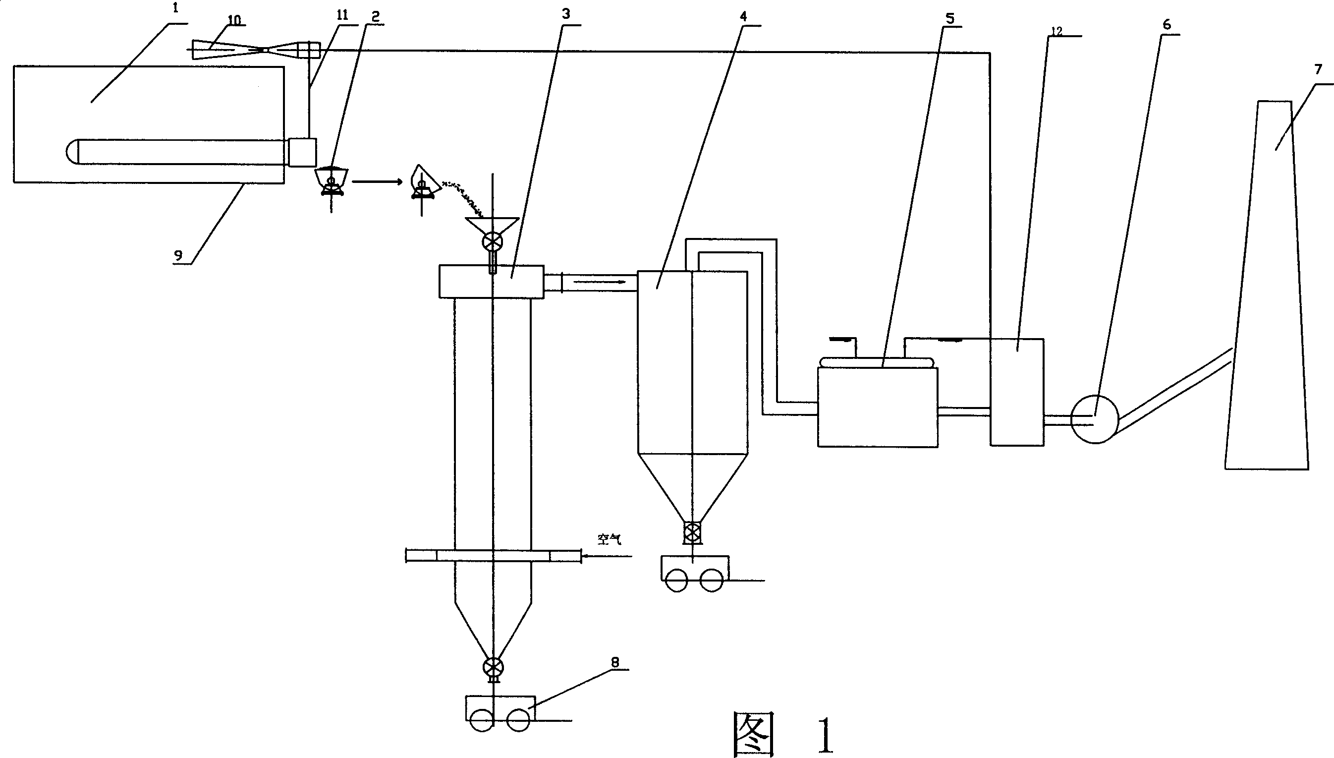
[0019] A vacuum pumping system that uses the waste heat of reducing slag to generate steam, as shown in Figure 1: it is composed of a reduction furnace 1, a fluidized bed 3, a dust collector 4, a waste heat boiler 5, an induced draft fan 6, and a chimney 7 connected in sequence through pipelines. In this way, a jet pump 10 connected to the gas outlet of the waste heat boiler 5 is provided on the upper part of the reduction furnace 1, a feeding bin is provided on the upper part of the fluidized bed 3, and a charging bin is provided on the lower part of the reduction furnace 1 to generate The reduced slag 2 is transported to the slag mine car 9 in the feeding bin of the fluidized bed 3. A bag dust collector 12 is provided between the waste heat boiler 5 and the induced draft fan 6, and a bag dust collector 12 is provided between the slag mine car 9 and the jet pump 10. Connected with a vacuum pipe 11, the dust collector 4 is a cyclone dust collector, and a cart 8 for dust removal...


PUM


Abstract

A system using residual heat of reduced slag to create vacuum comprises reduction furnace, fluidized bed, dust remover, residual heat boiler, draught fan and chimney. It is featured as setting jet injector being connected to air outlet of residual heat boiler on top of reduction furnace, utilizing residual heat generated by Mg reduced slag to produce steam through said system fir making reduction furnace be vacuumed.

Description

technical field [0001] The invention relates to a waste heat system which fully utilizes the reduction slag of metal magnesium, in particular to a system which uses the waste heat of the reduction slag to generate steam for vacuuming. Background technique [0002] The production process of metal magnesium requires a high temperature of 1200°C and a vacuum condition of 13.3Pa. At present, one method of realizing vacuum is completed by a vacuum unit, which consumes a lot of power; another method It uses the waste heat of the flue to generate steam through the waste heat boiler, and then introduces the steam into the steam jet pump to generate a vacuum; thus, the reducing slag generated in the production process of magnesium metal containing a large amount of heat is directly discharged and cooled, which not only causes the heat energy to not be fully utilized, And wasted a large amount of energy; Although the latter method has utilized waste heat, the heat of reducing slag has...

Claims


Application Information

Patent Timeline
Patent Type & Authority Applications(China)
IPC IPC(8): F27D17/00F22B1/04F04F5/20
CPCY02P10/25
Inventor 罗宝李文胜
Owner 宁夏华源冶金实业有限公司
Why Eureka
Try Eureka