Thermal rubber heat sink and its manufacturing method and circuit board and its manufacturing method

A production method and technology of thermally conductive adhesive, which are applied in the directions of printed circuit manufacturing, printed circuits, electrical components, etc., can solve the problems of short circuit, loud noise, ion pollution, etc. good effect

Inactive Publication Date: 2007-02-14
HUAWEI TECH CO LTD
View PDF0 Cites 9 Cited by
  • Summary
  • Abstract
  • Description
  • Claims
  • Application Information

AI Technical Summary

Problems solved by technology

Then the airflow produced by the cooling fan takes away the heat on the heat dissipation pad 5. In order to ensure good heat dissipation, a larger air volume is required, which will consume more electric energy, and the friction between the operation of the fan and the airflow will produce greater heat dissipation. Loud noise will cause noise pollution, and the cooling air will also bring serious ion pollution, resulting in a higher failure rate. In order to ensure the heat dissipation effect with less cooling air volume, there are currently two main methods to improve the heat dissipation effect:
[0005] One method is to expand the area of ​​the heat dissipation pad 5, but for a circuit board with a high-density layout, many electronic components with other functions will be soldered around the heat dissipation pad 5, and the degree of expanding the area of ​​the heat dissipation pad is limited. cannot grow infinitely
[0006] Another method is to add a surface mount heat sink 7 on the original heat dissipation pad 5, such as image 3 As shown, this method has a good effect on increasing the heat dissipation capacity, because the surface mount heat sink 7 must have a certain height, but, in some densely assembled equipment, the spacing between circuit boards is often smaller than that of surface mount heat sinks. The height required by the heat sink, the metal material of the surface mount heat sink 7 is easy to cause a short circuit between the circuit boards, which is not allowed, thus limiting the use of the surface mount heat sink 7

Method used


Image

  • Thermal rubber heat sink and its manufacturing method and circuit board and its manufacturing method
  • Thermal rubber heat sink and its manufacturing method and circuit board and its manufacturing method
  • Thermal rubber heat sink and its manufacturing method and circuit board and its manufacturing method

Examples


specific Embodiment approach

[0044] A preferred embodiment of the present invention is:

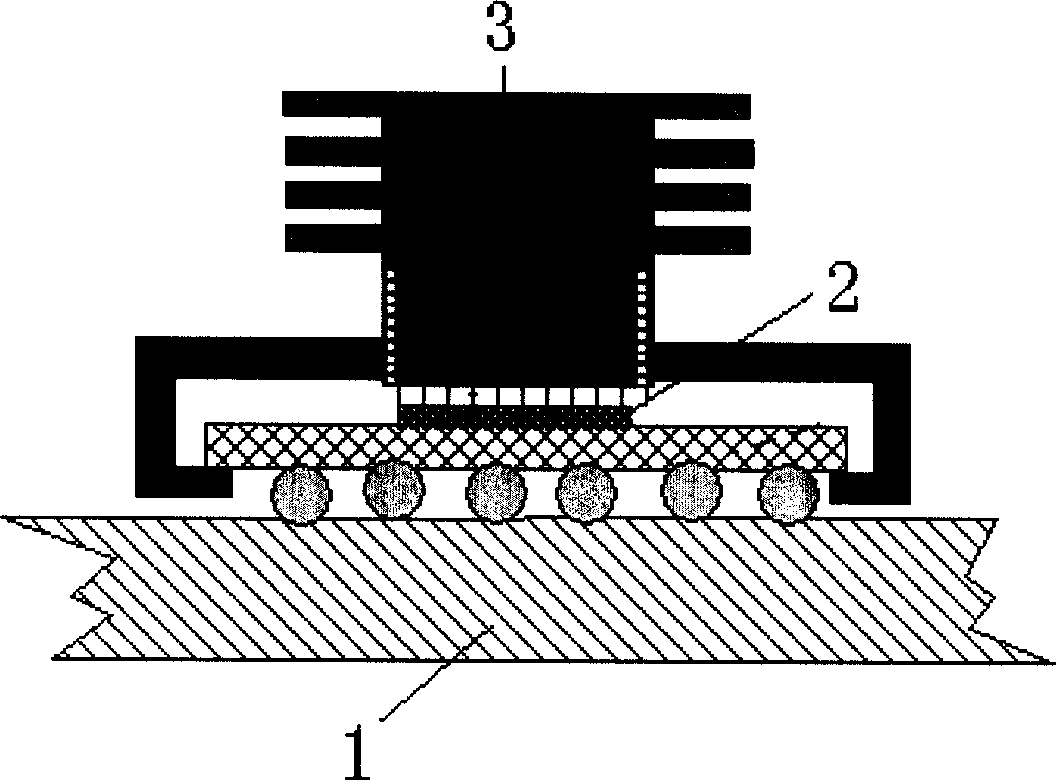
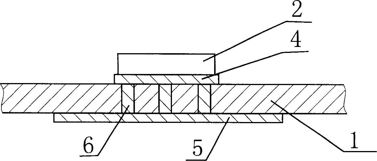
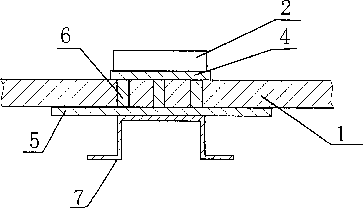
[0045] The thermally conductive glue radiator is designed as a sheet structure, made of thermally conductive glue that meets the predetermined requirements and is insulated. The predetermined thermal conductivity of the thermally conductive glue is selected according to the heat dissipation requirements of the device that needs to be dissipated. The thermal conductivity is greater than 0.5W / mK is enough, the preferred range is 2~5W / mK, the definition of thermal conductivity is: how much W energy can be transmitted per m length and per K temperature, and the unit is W / mK. Among them, "W" refers to the unit of thermal power in watts, "m" refers to the unit of length in meters, and "K" refers to the unit of absolute temperature. The larger the thermal conductivity, the better the thermal conductivity.

[0046] There are two ways to make and install thermal paste radiators:

[0047] One is the flow coating method: hea...


PUM


Abstract

The invention discloses a radiator with thermal conductive gum and its producing method, as well as the electric circuit board with this radiator and its producing method. A continuous thermal conductive film, which is produced by the gum with good thermal conductivity and insulation, is formed by covering the electric circuit board. It can increase heat dissipation area of the electrical component or heat dissipating soldering-pan without changing the design of the circuit board with simple structure, convenient production, installation and use, which area of heat dissipation is not influenced by the arrangement of the electrical components on the circuit board. Different methods can be selected to produce the radiator according to the needs. One is to coat this gum on the board directly. Another is to produce the gum radiator first, and then cut the size of board to paste on it.

Description

technical field [0001] The invention relates to a heat dissipation technology, in particular to a radiator and a manufacturing method thereof, as well as a circuit board using the radiator and a manufacturing method thereof. Background technique [0002] Some integrated circuits with high power density will be used in circuit board design. In order to ensure that the integrated circuit will not be damaged due to excessive temperature rise during operation, it is usually necessary to add a radiator to it to help dissipate heat. The shape and installation method of the radiator It can be varied, but most of its principles are to help heat dissipation by increasing the heat dissipation area. At present, the commonly used radiators mainly include the following types: [0003] One is a backpack radiator, such as figure 1 As shown, the piggyback heat sink 3 is directly attached to the integrated circuit module 2 on the circuit board 1. This type of heat sink has a large volume a...

Claims


Application Information

Patent Timeline
Patent Type & Authority Applications(China)
IPC IPC(8): H05K7/20H05K3/00
Inventor 陈普养徐焰郏宇飞
Owner HUAWEI TECH CO LTD
Why Eureka
Try Eureka