Electroplating in presence of co2

A CO2, CH2 technology, applied in the field of environmental response, can solve the problem that there is no information related to the surfactant and the coating operation of the coating

Inactive Publication Date: 2007-02-21
DAIKIN IND LTD
View PDF2 Cites 15 Cited by
  • Summary
  • Abstract
  • Description
  • Claims
  • Application Information

AI Technical Summary

Problems solved by technology

[0009] Furthermore, with regard to this supercritical plating technology, there has been no

Method used


Image

  • Electroplating in presence of co2
  • Electroplating in presence of co2
  • Electroplating in presence of co2

Examples


Embodiment 1

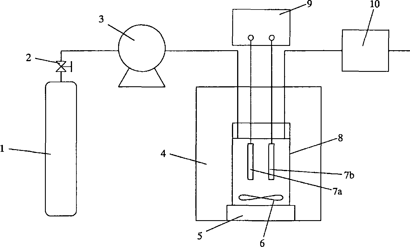
[0237] figure 1 is the device used in the examples of the present invention.

[0238] Add 20cc nickel plating bath (Watt bath: nickel sulfate 280g / L, nickel chloride 60g / L, boric acid 50g / L, amount of gloss agent) in the high pressure container 8 of 50cc in internal volume, relative plating bath is 0.3wt% F(CF(CF 3 ) CF 2 O) 3 CF(CF 3 )COO(CH 2 CH 2 O) 2 CH 3 , mounted and sealed a degreased brass plate on the cathode, and a pure nickel plate (each with a surface area of ​​4 cm) on the anode and sealed 2 ), after heating up to 50°C in the constant temperature tank 4, use the infusion pump 3 and the pressure regulator 10 to seal the CO 2 Up to 10MPa. By using the stirrer 5 to rotate the rotor 6 at 500r.p.m, the CO 2 - Plating solution, then at 5A / dm 2 Electricity was applied for 6 minutes to perform nickel plating. After the energization was completed, the pressure was reduced, and then the cathode plate was taken out, sufficiently washed with water, and the surfac...

Embodiment 2

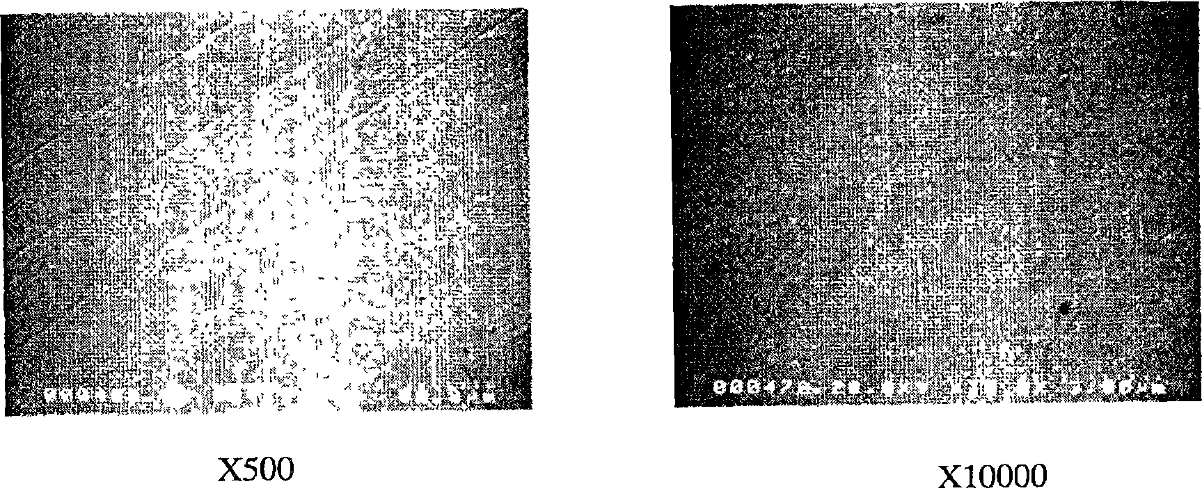
[0240] as having CO 2 For non-ionic compounds with affinity moieties use H(CF 2 ) 6 COOCH 2 CH 3 , except that, plating was performed by the same method as in Example 1.

[0241] The obtained scanning electron micrographs are shown in image 3 middle.

Embodiment 3

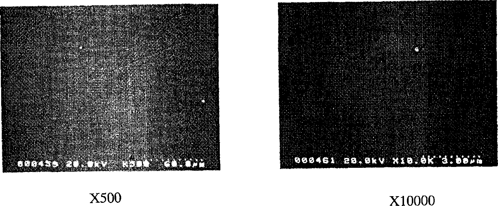
[0243] as having CO 2 Non-ionic compounds with affinity part use F(CF 2 ) 6 (CH 2 ) 10 H, plating was performed by the same method as Example 1 except that.

[0244] The obtained scanning electron micrographs are shown in Figure 4 middle.


PUM


Abstract

A method for performing electroplating in the co-presence of CO2 and an aqueous solution containing a metal salt is characterized in that CO2 is in a liquid, subcritical or supercritical state and a nonionic compound having a CO2 affinity portion is further added into the system where the aqueous solution and CO2 are co-present. By this method, the electrochemical reaction proceeds more efficiently and there can be formed a very good metal coating.

Description

technical field [0001] The present invention relates to CO 2 An environmental response technology that replaces solvents. More specifically, it involves CO 2 Efficiency technology for electrochemical reaction of solvent and electroplating technology using this technology. Background technique [0002] Due to the conspicuousness of environmental problems, the use of CO 2 Attention has been paid to technologies that can replace highly toxic organic solvents as solvents. And, if it is possible to 2 If the intermediate treatment compound is used, the cost of wastewater treatment may be greatly reduced, and the application in industrial fields with high wastewater treatment costs such as dyeing and plating has attracted special attention. In such a technical background, it is disclosed that an aqueous metal salt solution and CO 2 A technique of electroplating by suspension (Patent Document 1, Non-Patent Documents 1 and 2). [0003] According to the information disclosed in...

Claims


Application Information

Patent Timeline
IPC IPC(8): C25D3/02B01J3/00
Inventor 永井隆文藤井和久浅井英明
Owner DAIKIN IND LTD
Why Eureka
Try Eureka