Pressure vessel liner and method for manufacturing the same

A pressure vessel, liner technology

Inactive Publication Date: 2007-02-21
RESONAC HOLDINGS CORPORATION
View PDF0 Cites 13 Cited by
  • Summary
  • Abstract
  • Description
  • Claims
  • Application Information

AI Technical Summary

Problems solved by technology

However, if the bushing is subjected to a greater force along its longitudinal direction, the stress concentration acts on the welded joint of the main body and the top plate, which may cause the bushing to break at the joint part, because the reinforcement wall of the main body is not connected to the reinforcement of the top plate wall
In order to prevent such breakage, the thickness of the helically wound reinforcement layer of the pressure vessel needs to be increased, which brings about a problem of greater weight
In addition, when forming a helically wound fiber layer, the fibers may break due to sliding contact or due to being caught, which cannot provide the required pressure resistance

Method used


Image

  • Pressure vessel liner and method for manufacturing the same
  • Pressure vessel liner and method for manufacturing the same
  • Pressure vessel liner and method for manufacturing the same

Examples


Embodiment 1

[0066] This example is in Figures 1 to 9 shown in .

[0067] figure 1 The pressure vessel liner of this embodiment is shown. figure 2 A pressure vessel for high pressure hydrogen in which this liner is used is shown. Figures 3 to 9 A method for manufacturing a pressure vessel liner is shown.

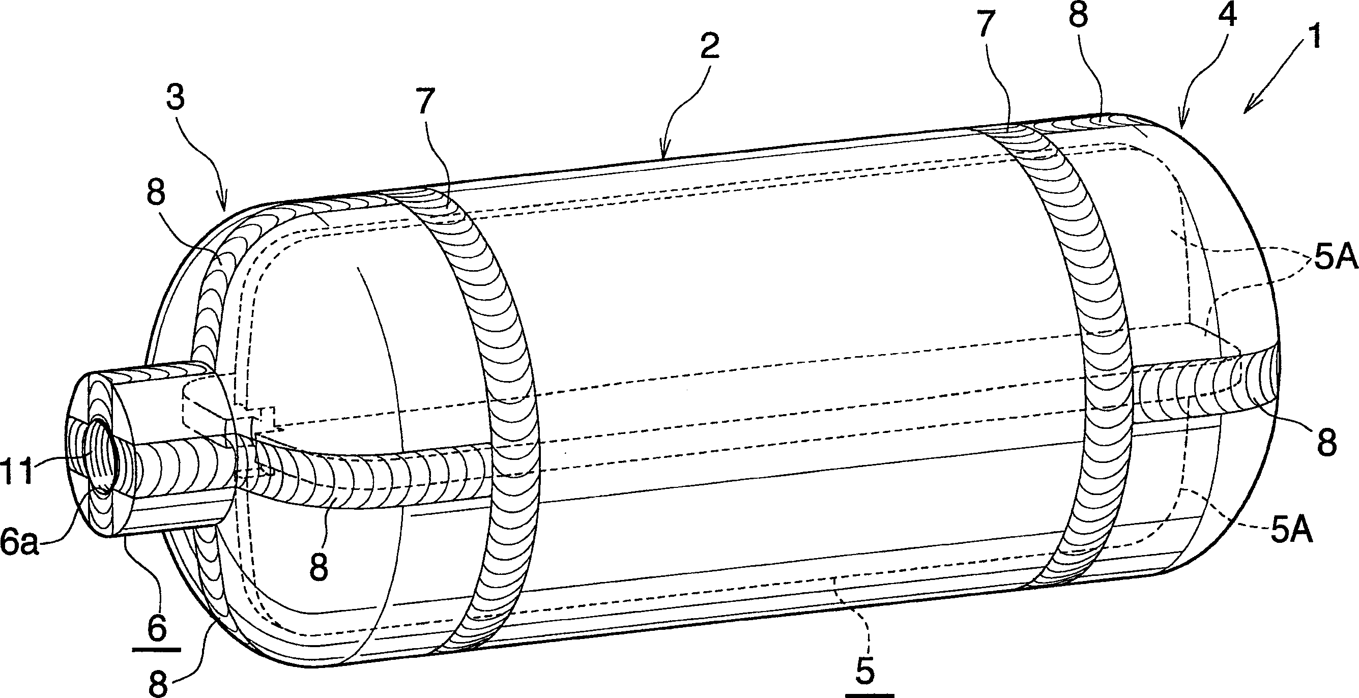
[0068] refer to figure 1 , a pressure vessel liner 1 comprising an aluminum body 2 open at its opposite ends, and aluminum top plates 3, 4 each in the form of an outwardly projecting dome for closing each end opening.

[0069] The main body 2 internally has a reinforcing member 5 integrated with the main body 2 and extending longitudinally of the main body 2, and the reinforcing member divides the interior of the main body 2 into a plurality of spaces. The main body 2 and the reinforcement 5 are integrally extruded using one of JIS A2000 alloy, JIS A5000 alloy, JIS A60000 alloy, and JIS A7000 alloy. The reinforcement 5 includes a plurality of, for example, four reinforcement wal...

Embodiment 2

[0084] This example is in Figure 10-15 shown in .

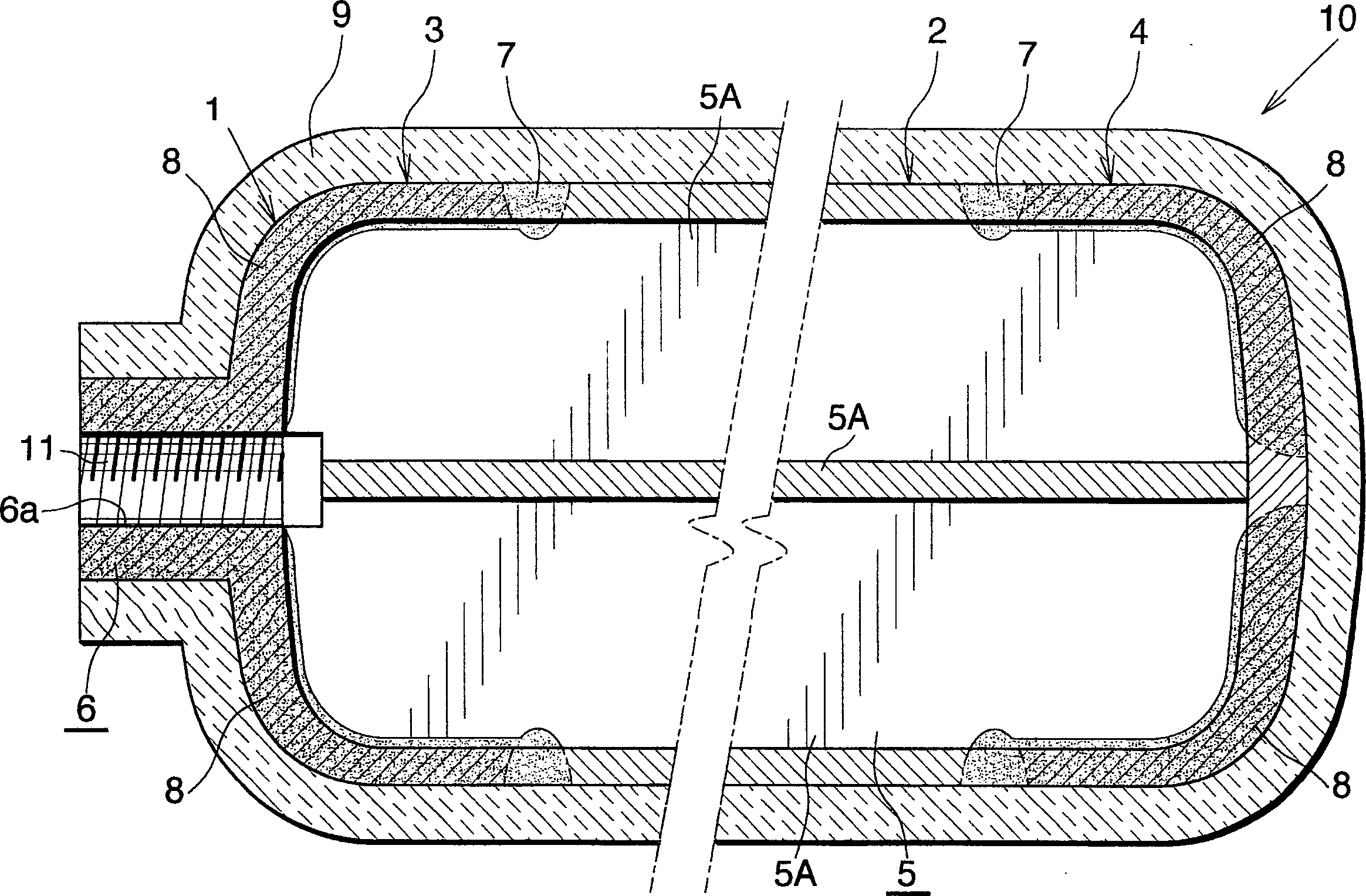
[0085] In the case of the pressure vessel liner 30 of this embodiment, on one of the top plates 31 is provided an interface portion 32 having an inner peripheral surface defining a hole 32 a extending through the interface portion 32 . The junction of the inner peripheral surface and the inner surface of the top plate 31 is circular (see Figure 11 ). The interface portion 32 is internally threaded at 11 other than at the circular portion 32b. The length of the internally threaded portion 11 is equal to the entire length of the through hole 6a of Embodiment 1. Apart from this feature, the liner 30 of this embodiment is identical to the pressure vessel liner 1 of the first embodiment described above.

[0086] Such as Figure 11 As shown, the pressure vessel liner 30 of Embodiment 2 is entirely covered with a fiber-reinforced resin layer 9 made of, for example, carbon fiber-reinforced resin so as to be used as a high-pres...

Embodiment 3

[0092] This example is in Figure 16 and 17 shown in .

[0093] Except that the top plate 41 having no interface portion 6 in the form of an outwardly protruding dome is integrally provided with the main body 2, and the reinforcing member 42 including a plurality of reinforcing walls 42A and having the same shape as the reinforcing member 5 of Embodiment 1 is independent of the The structure of the pressure vessel liner 40 of this embodiment is the same as that of the pressure vessel liner 1 of the embodiment 1 except that the main body 2 is manufactured, placed in the main body 2 and connected with the main body 2 by friction stirring. The joint of the main body 2 and the reinforcement wall 42A of the reinforcement 42 has a weld 43 . The connection length of the main body 2 to the stiffener 42 is preferably at least 60% of the entire length of the stiffener 42 and, according to this embodiment, the stiffener 42 is attached to the main body 2 over the entire length of the ma...


PUM


Abstract

A pressure vessel liner includes a tubular trunk, and head plates for closing opposite end openings of the trunk. Provided inside the trunk is a reinforcing member integral with the trunk and extending longitudinally of the trunk for dividing the interior of the trunk into a plurality of spaces. The two head plates are joined respectively to opposite ends of the reinforcing member. The pressure vessel liner has an enhanced pressure resistant strength against longitudinal forces.

Description

[0001] Cross References to Related Applications [0002] This application is an application filed under 35 U.S.C. §111(a) and claims the filing-date benefit of provisional application No. 60 / 544,358, which was filed under 35 U.S.C. §111( b) Submitted on February 17, 2004. technical field [0003] The present invention relates to a liner for a pressure vessel for storing hydrogen or natural gas used as fuel for power generation, or for storing oxygen, for example in the automobile industry, household industry, military industry, aviation industry, pharmaceutical industry, etc. And a method of producing the bushing. [0004] As used herein and in the appended claims the term "aluminum" includes aluminum alloys in addition to pure aluminum. Background technique [0005] To control air pollution, efforts have been made in recent years to develop natural gas vehicles and fuel cell vehicles that produce clean emissions. Pressure vessels filled with fuel natural gas or hydrogen ...

Claims


Application Information

Patent Timeline
Patent Type & Authority Applications(China)
IPC IPC(8): F17C1/02B60L11/18F02B43/00F02M21/02F17C1/06F17C1/08F17C1/14F17C1/16H01M8/04
CPCF17C2201/0166Y02E60/321F17C2270/07F17C2203/0619F17C2203/0665F17C2260/011F17C2209/234F17C1/14F17C2203/067F17C2270/02F17C2201/056F17C2223/035Y02E60/50F17C1/06F17C2221/011F17C2260/012F17C2270/0184F17C2201/0119F17C2205/0397F17C2205/0323F17C2270/0168F17C2201/0109F17C2265/07F17C2270/0763F17C2260/013F17C2203/0648F17C2270/05F17C2209/232F17C2203/0668F17C2221/033F17C2221/012F17C1/08F17C2203/0646F17C1/16F17C2270/0194F17C2223/0123F17C2203/0604F17C2209/222F17C2203/013Y02E60/32Y02T10/7072F17C1/00F17C1/02
Inventor 岛田毅昭吉田泰树桑原宏和纳康弘菅野快治川又保二山崎英世
Owner RESONAC HOLDINGS CORPORATION
Why Eureka
Try Eureka