Location method for nano materials synthesis used catalyst

A nanomaterial and catalyst technology is applied in the field of positioning of catalysts for nanomaterial synthesis, which can solve the problems of no practical value, no deposition, substrate contamination, etc. The effect of strong practicality

Inactive Publication Date: 2007-02-28
PEKING UNIV
View PDF0 Cites 8 Cited by
  • Summary
  • Abstract
  • Description
  • Claims
  • Application Information

AI Technical Summary

Problems solved by technology

The main disadvantage of these fixed-site catalyst methods is that no matter it is spin-coating catalyst solution or self-assembly, since the substrate contacts a large amount of catalyst solution, other parts on the substrate will be contaminated during the peeling process.
However, the size of the catalyst particles r

Method used


Image

  • Location method for nano materials synthesis used catalyst
  • Location method for nano materials synthesis used catalyst
  • Location method for nano materials synthesis used catalyst

Examples


Embodiment 1

[0036] Embodiment 1, the location of the catalyst for the synthesis of carbon nanotubes

[0037] 1. The positioning of the catalyst

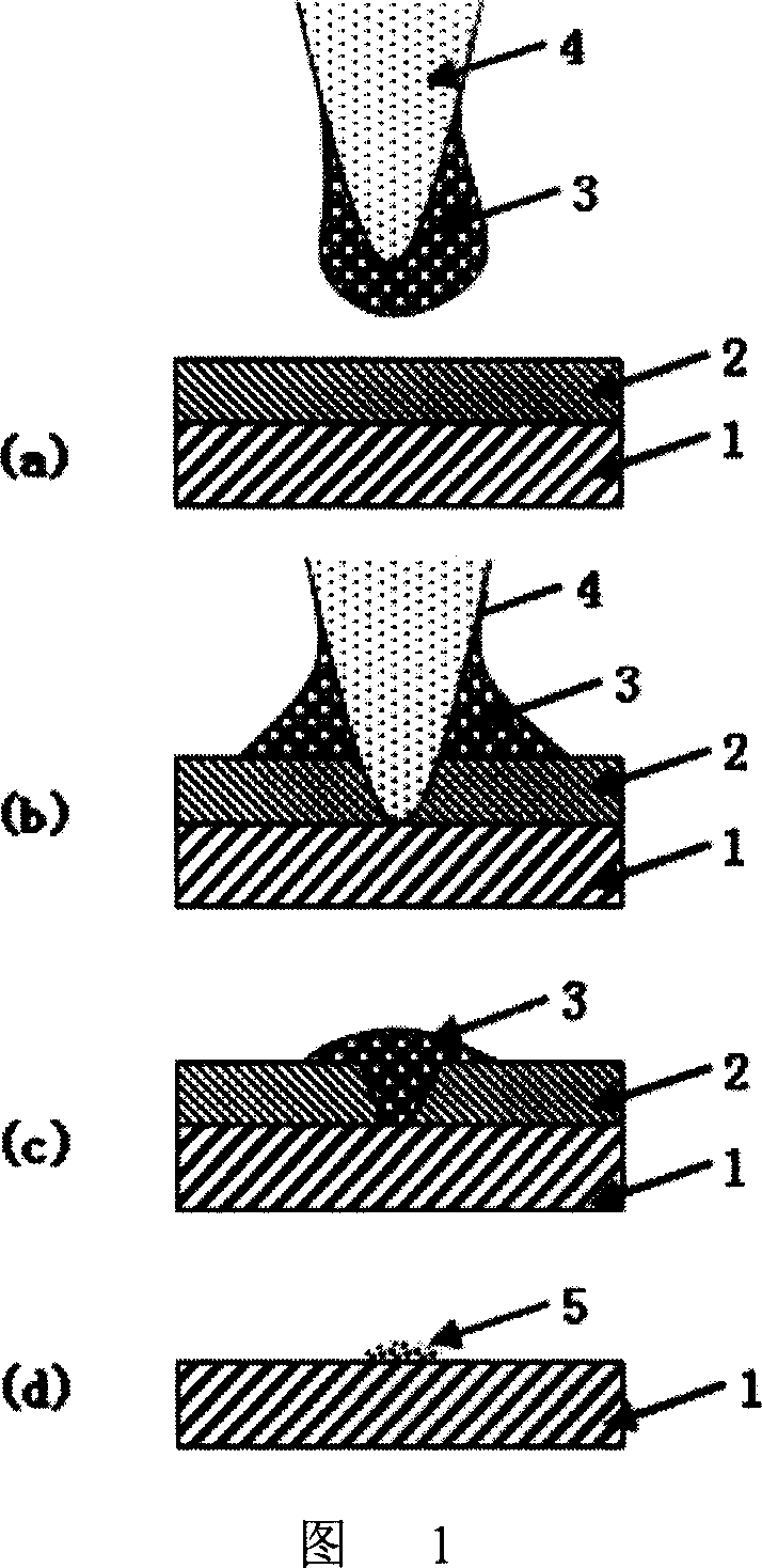
[0038] A schematic diagram of the process flow for positioning a catalyst is shown in Figure 1. Among them (a) in Fig. 1 is that the needle point 4 that has catalyst solution 3 approaches the substrate 1 that is spin-coated with photoresist 2; Among Fig. 1 (b) is that the needle point 4 that has catalyst solution 3 punctures photoresist 2, and catalyst solution 3 contacts the substrate 1; (c) in Fig. 1 shows that after the atomic force microscope tip 4 leaves, the catalyst solution 3 remaining in the groove of the scratched photoresist 2 contacts the substrate 1; (d) in Fig. 1 shows stripping the photoresist, After firing, the obtained catalyst 5 is positioned on the surface of the substrate 1 .

[0039] The specific steps are as follows:

[0040] 1. Clean the substrate: use quartz as the substrate, cut the quartz into small pieces of 1cm×1cm s...

Embodiment 2

[0047] Embodiment 2, the positioning of the catalyst for the synthesis of carbon nanotubes

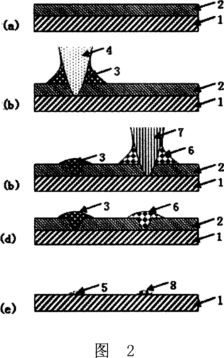
[0048] A schematic process flow diagram of the method for positioning the two catalysts is shown in FIG. 2 . Among Fig. 2 (a) is the substrate 1 that is spin-coated with photoresist 2; Among Fig. 2 (b) is that the needle tip 4 that has the first kind of catalyst solution 3 scratches photoresist 2, and the first kind of catalyst solution 3 contacts substrate 1 ; (c) in Fig. 2 is after positioning the first catalyst solution 3, scratches the photoresist 2 with the needle point 7 that has the second catalyst solution 6, and the second catalyst solution 6 contacts the substrate 1; (d) is the first catalyst solution 3 and catalyst solution 6 positioned in the groove of the photoresist 2; among Fig. 2 (e) is the catalyst 5 (catalyst) positioned on the surface of the substrate 1 obtained after peeling off and burning solution 3) and catalyst 8 (obtained from catalyst solution 6).

[0049] 1...


PUM

PropertyMeasurementUnit
Thicknessaaaaaaaaaa
Diameteraaaaaaaaaa
Diameteraaaaaaaaaa

Abstract

The invention relates to a method for positioning the catalyst of carbon composition nanometer tube, wherein it comprises: (1), coating photo resist on the substrate to be dried; (2), preparing catalyst solution; (3), using the needle of atomic force microscope with catalyst solution to pass through the photo resist coat, to transfer the solution on the needle sharp to the substrate; (4), removing photo resist to obtain the substrate positioned with catalyst image. The invention can obtain the catalyst image whose line width is in 1 mum, point diameter is in 1micrometer, and position accuracy is in 5 mum, while it is at centimeter range; and it can accurately position at least two kinds of catalysts on one substrate. Compared with common nanometer dip pen print technique, the invention can deposit more material, and the deposited catalyst can composite carbon nanometer tube.

Description

technical field [0001] The invention relates to a positioning method of a catalyst used for nanometer material synthesis. Background technique [0002] Due to its unique structure, carbon nanotubes have excellent properties in many aspects, and are a new type of nanomaterials with very good application prospects in many fields. In many cases, for the purpose of research and application, it is necessary to synthesize single-walled carbon nanotubes on a flat substrate surface. The premise and core of the fixed-point synthesis of carbon nanotubes is the positioning of the catalyst, and the size of the catalyst particles required for the synthesis of single-walled carbon nanotubes is generally around a few nanometers. How to precisely position the catalyst nanoparticles on the substrate surface for single-walled carbon nanotubes The synthesis of nanotubes has important value and significance. [0003] At present, there are many technologies for locating catalysts. The position...

Claims


Application Information

Patent Timeline
IPC IPC(8): G03F7/00C01B31/02
Inventor 张锦张永毅张依刘忠范
Owner PEKING UNIV
Why Eureka
Try Eureka