Inertial electricity generating device for portable electronic equipment

A technology for portable electronic equipment and power generation devices, which is applied to battery circuit devices, electromechanical devices, circuit devices, etc., can solve the problems that electronic devices cannot be integrated, the working place of the charging device is limited, and the structure is complicated, and it can meet the requirements of short-term Work, simple structure, compact effect

Inactive Publication Date: 2007-02-28
NAT UNIV OF DEFENSE TECH
View PDF3 Cites 16 Cited by
  • Summary
  • Abstract
  • Description
  • Claims
  • Application Information

AI Technical Summary

Problems solved by technology

[0003] The technical problem to be solved by the present invention is to solve the shortcomings of the portable electronic equipment charging device, such as limited working place or complex structure, bulky size, and inability to be integrated with electronic equipment, etc., and provide a charging device that uses human body's daily behavior to generate energy, which is small in size and can be combined with the electronic equipment. Electronic equipment is integrated or a power generation device that is easily carried by the human body can effectively prolong the working time of a portable electronic device; when the battery energy is exhausted, the specific behavior of the human body can meet the short-time work requirements of the portable electronic device

Method used


Image

  • Inertial electricity generating device for portable electronic equipment
  • Inertial electricity generating device for portable electronic equipment
  • Inertial electricity generating device for portable electronic equipment

Examples


Embodiment Construction

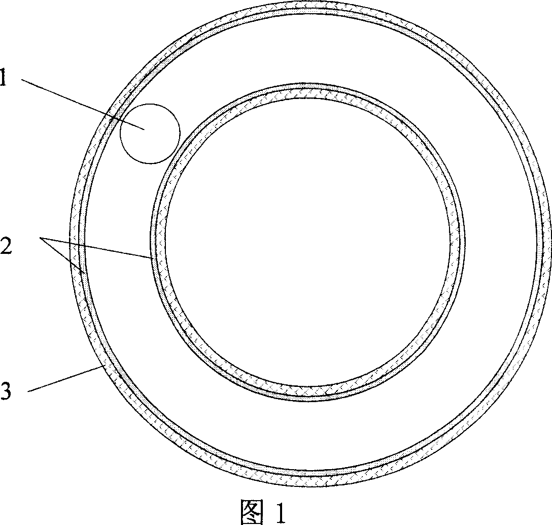
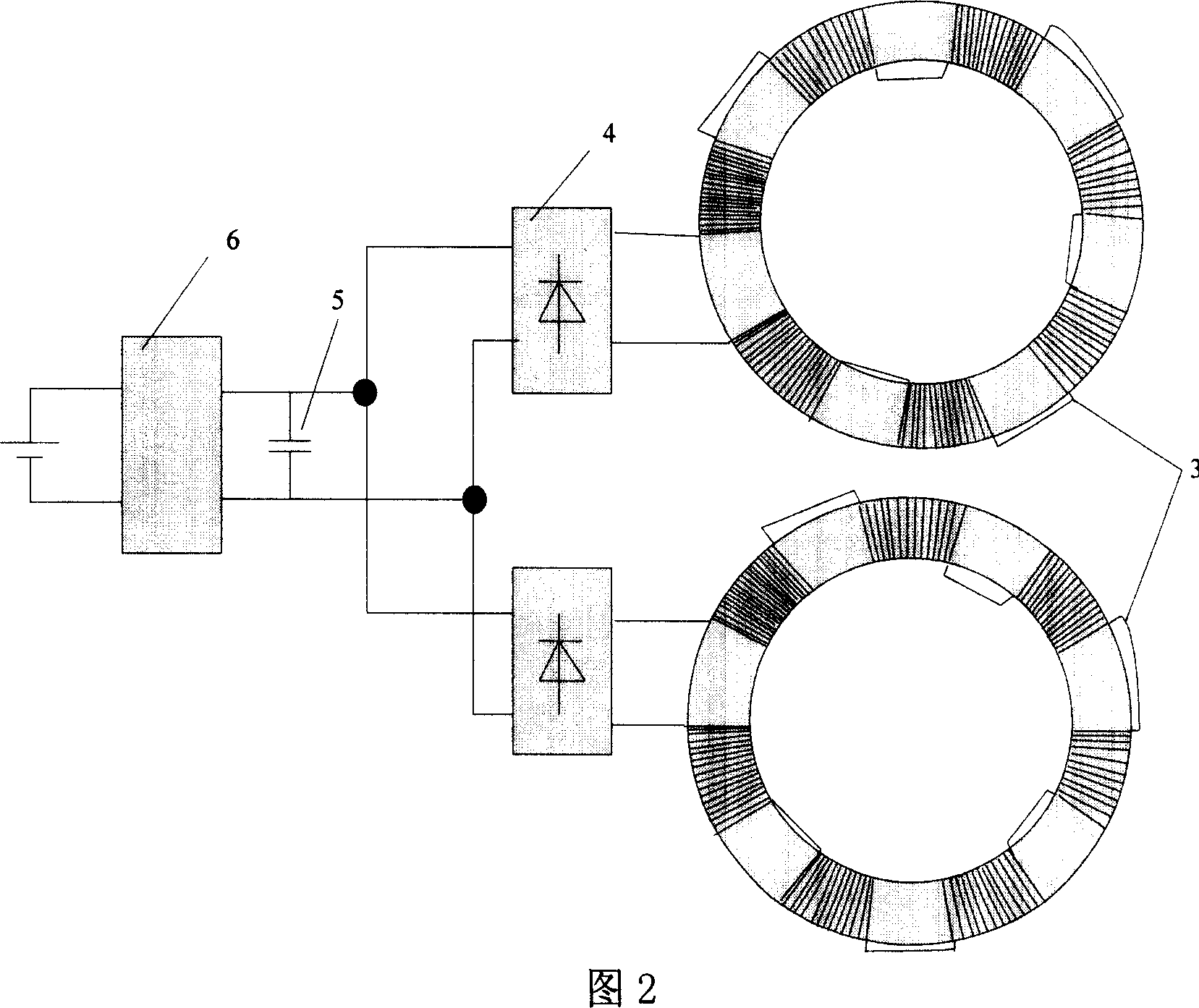
[0036]Fig. 1 is a schematic diagram of the basic structure of an embodiment of a power generation device based on free motion of an inertial ball. The power generating device is composed of an inertia ball 1 , an annular guide groove 2 and a coil 3 . Inertia ball 1 diameter D=15mm, is made of permanent magnetic material, has strong magnetism. The length L=210mm of the annular guide groove 2, the cross section of the inner wall along the center of the circle is circular, the diameter is greater than 15mm and less than 15.5mm, made of non-ferromagnetic material, and the wall thickness of the annular guide groove is less than 0.5mm. The inertia ball 1 and the annular guide groove 2 are clearance fit, and the inertia ball 1 can move freely in the annular guide groove 2 . The coil 3 is wound on the annular guide groove 2, and the coil 3 adopts an enameled wire with a diameter of 0.15 mm. The coil 3 is divided into two groups on the electrical connection, and is wound on the same g...


PUM


Abstract

The invention relates to an inertia generator of portable electric device, formed by movable inertia block and winding. Wherein, it via body motion obtains relative motion between inertia block and winding to change the magnetic flux of winding, to generate induced electromotive force. The invention uses inertia ball, annular groove and winding to form the generator based on free motion of inertia ball; the electromagnetic couple generator formed by rotor, stator and axle based on rotation inertia block; and speed-increase generator formed by inertia rotor, gear speed increaser and direct-current generator based on rotation inertia block. The invention has small volume and simple structure, to be integrated with electric device or separated from electric device. The invention can prolong the service time of electric device, via one charge.

Description

technical field [0001] The invention relates to a power supply device, in particular to a power generation device for portable electronic equipment. Background technique [0002] Portable electronic devices such as mobile phones, PDAs, and MP3 players have been widely used. They are generally battery powered, but they only work when the battery is charged. In places where charging is not possible, such as outdoors, if the battery is dead, it will cause great inconvenience. Patent 200320108024 proposes a built-in solar mobile phone charging device, which uses photovoltaic cells to convert solar energy into electrical energy, but when the mobile phone is in a pocket or at night, the charging device cannot work. Patent 200420000836 proposes a mobile phone emergency charger, the charger uses gear transmission to drive the generator, and people drive the gear to move through the buckle; patent 200320103286 proposes a hand-operated generator, which drives the gear transmission ...

Claims


Application Information

Patent Timeline
Patent Type & Authority Applications(China)
IPC IPC(8): H02K35/02H02J7/32H02K7/116F03G5/06
Inventor 单庆晓潘孟春杨俊
Owner NAT UNIV OF DEFENSE TECH
Why Eureka
Try Eureka