Humidity controller

A humidity control and housing technology, applied in air conditioning systems, separation methods, heating methods, etc., can solve problems such as troublesome installation operations, and achieve the effects of easy installation operations, improved efficiency, and reduced pressure loss

Inactive Publication Date: 2007-02-28
DAIKIN IND LTD
View PDF3 Cites 7 Cited by
  • Summary
  • Abstract
  • Description
  • Claims
  • Application Information

AI Technical Summary

Problems solved by technology

[0011] In addition, if part of the refrigerant circuit is arranged outside the housing, the refrigerant circuit must be connected with piping when installing the humidity control device, and the installation work is troublesome.

Method used


Image

  • Humidity controller
  • Humidity controller
  • Humidity controller

Examples


Embodiment Construction

[0113] Embodiments of the present invention will be described below with reference to the drawings. The following embodiments are preferred illustrations in nature and do not limit the scope of the present invention, its applications and uses.

[0114] Embodiment 1 of the invention

[0115] Embodiment 1 of the present invention will be described in detail below with reference to the drawings.

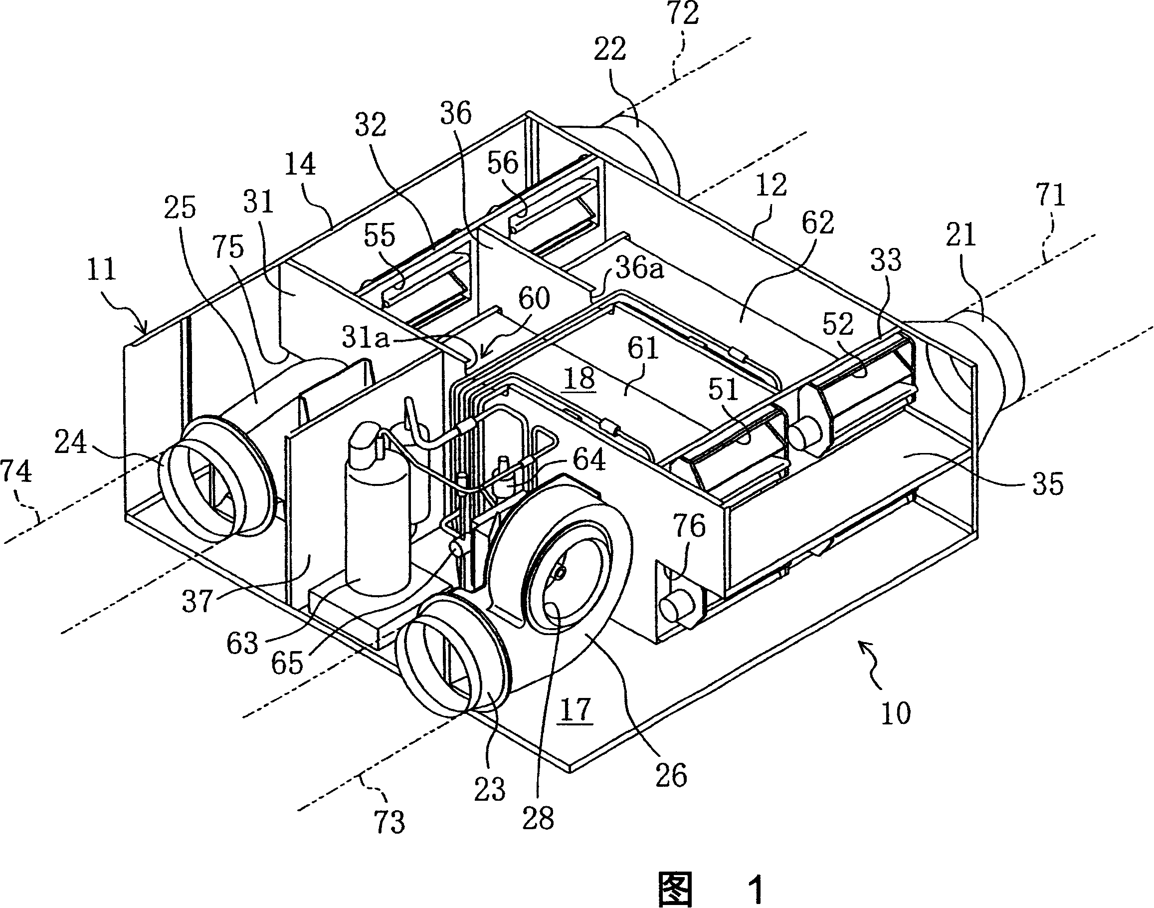
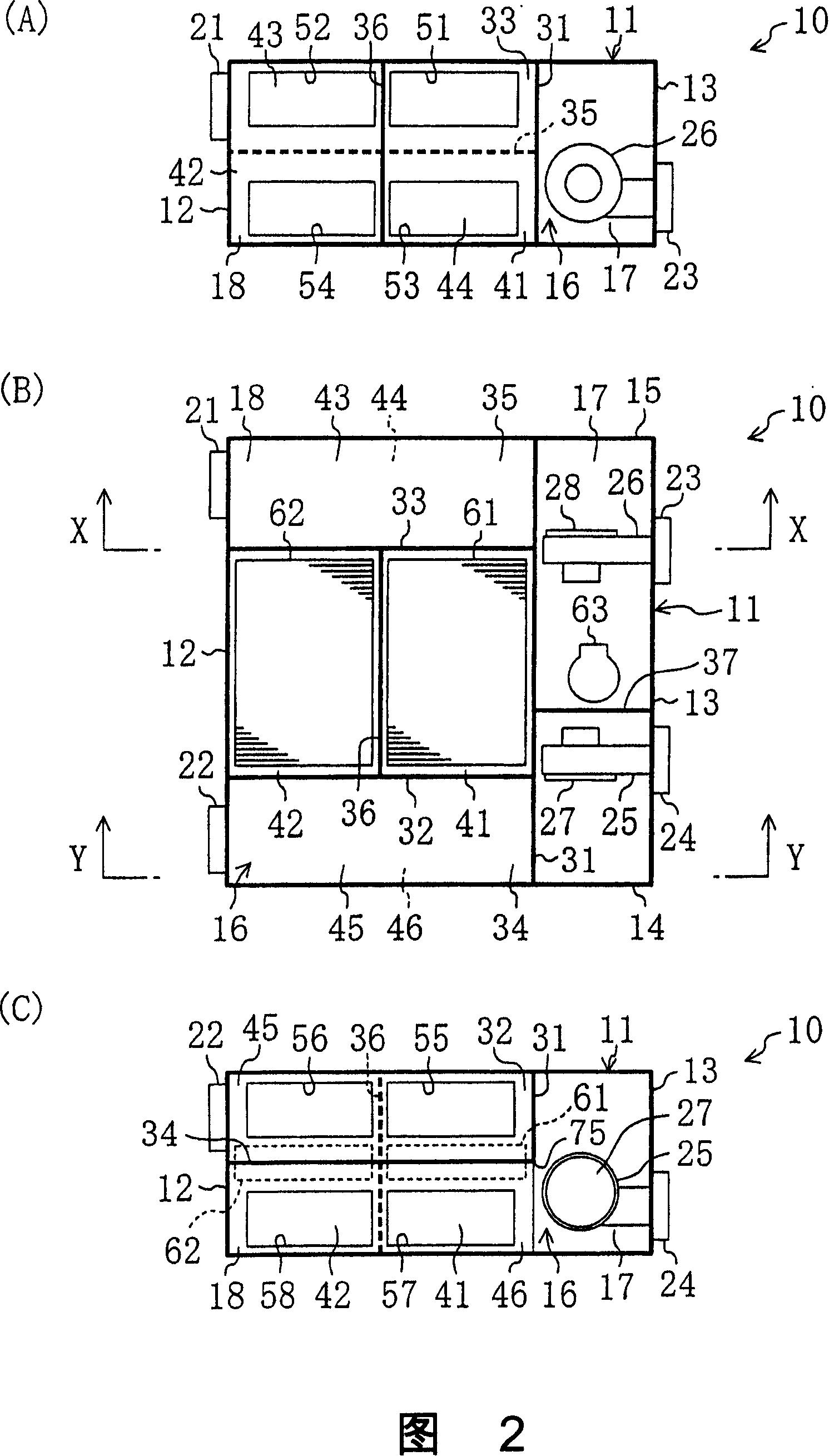
[0116] As shown in FIG. 1 and FIG. 2, the humidity control device 10 of this embodiment is used for dehumidifying and humidifying indoor air, has a box-shaped casing 11, and is arranged horizontally on the back of a ceiling, for example. In FIG. 2 , figure (B) is a top view, figure (C) is a view from the Y direction, and figure (A) is a view from the X direction. "Right" and "left" described below all refer to directions in FIG. 2 . Fig. 1 is a perspective view of the humidity control device 10 of Fig. 2(B) seen from the upper right.

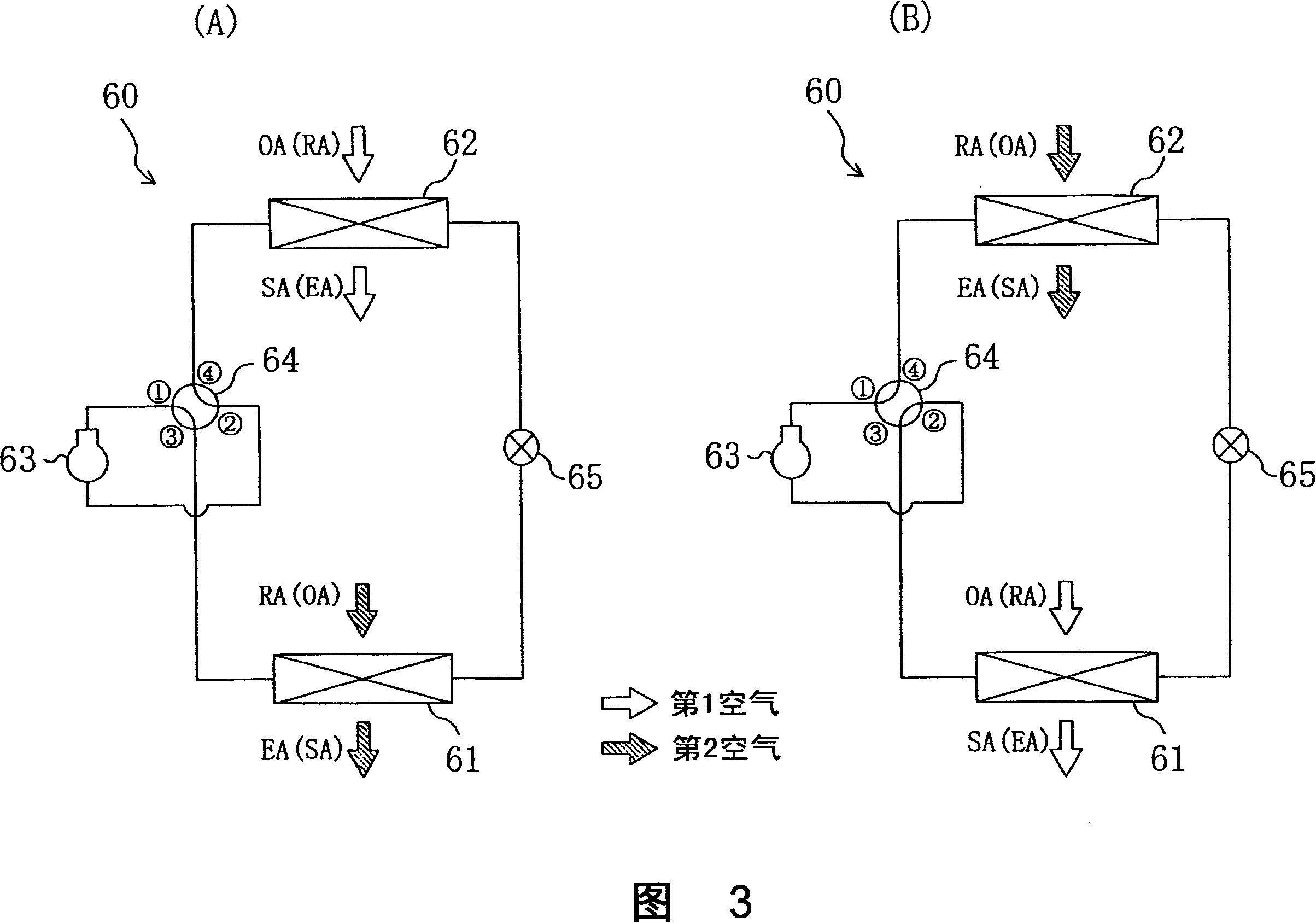
[0117] The refrigerant circuit 60 and the like ...


PUM


Abstract

A humidity controller (10) is provided with a refrigerant circuit (60). The refrigerant circuit (60) has first and second heat exchangers (61, 62) carrying an adsorptive agent and circulates a refrigerant to perform a freezing cycle. Further, in the refrigerant circuit (60), the direction of circulation of the refrigerant is reversible. The first and second heat exchangers (61, 62) are installed in a casing (11). In the humidity controller (10), air flow paths are switched so that first air passes through either of the heat exchangers (61, 62) that works as an evaporator and second air passesthrough the other that works as a condenser. A compressor (63), an expansion mechanism (65), and a four-way selector valve (64) of the refrigerant circuit (60) are installed in the casing (11) together with the heat exchangers (61, 62).

Description

technical field [0001] The present invention relates to a humidity control device for adjusting the humidity of air, in particular to a technique for performing refrigeration cycle for regeneration and cooling of adsorbent. Background technique [0002] Conventionally, for example, there is a humidity control device disclosed in Patent Document 1 that uses an adsorbent and a refrigeration cycle to adjust the humidity of air. The humidity control device has two adsorption units. Each adsorption unit includes a mesh container filled with an adsorbent and a refrigerant tube of a drum mesh container. The refrigerant pipes of each adsorption unit are connected to a refrigerant circuit that performs a refrigeration cycle. The humidity control device is provided with a damper for switching the air sent to each adsorption unit. [0003] During the operation of the humidity control device, the compressor of the refrigerant circuit is operated, and a refrigeration cycle is performe...

Claims


Application Information

Patent Timeline
Patent Type & Authority Applications(China)
IPC IPC(8): F25B29/00B01D53/26F24F3/14F25B13/00F25B31/00
CPCF24F3/1429F24F3/1411
Inventor 薮知宏池上周司成川嘉则
Owner DAIKIN IND LTD
Why Eureka
Try Eureka