
Data sampling monitoring control device and method for micro combustion steam turbine

A gas turbine, data acquisition technology, applied in the field of information

Inactive Publication Date: 2007-03-07
NORTHEASTERN UNIV
View PDF0 Cites 13 Cited by
  • Summary
  • Abstract
  • Description
  • Claims
  • Application Information

AI Technical Summary

Problems solved by technology

At present, the system has not been applied in the field of micro gas turbine

Method used

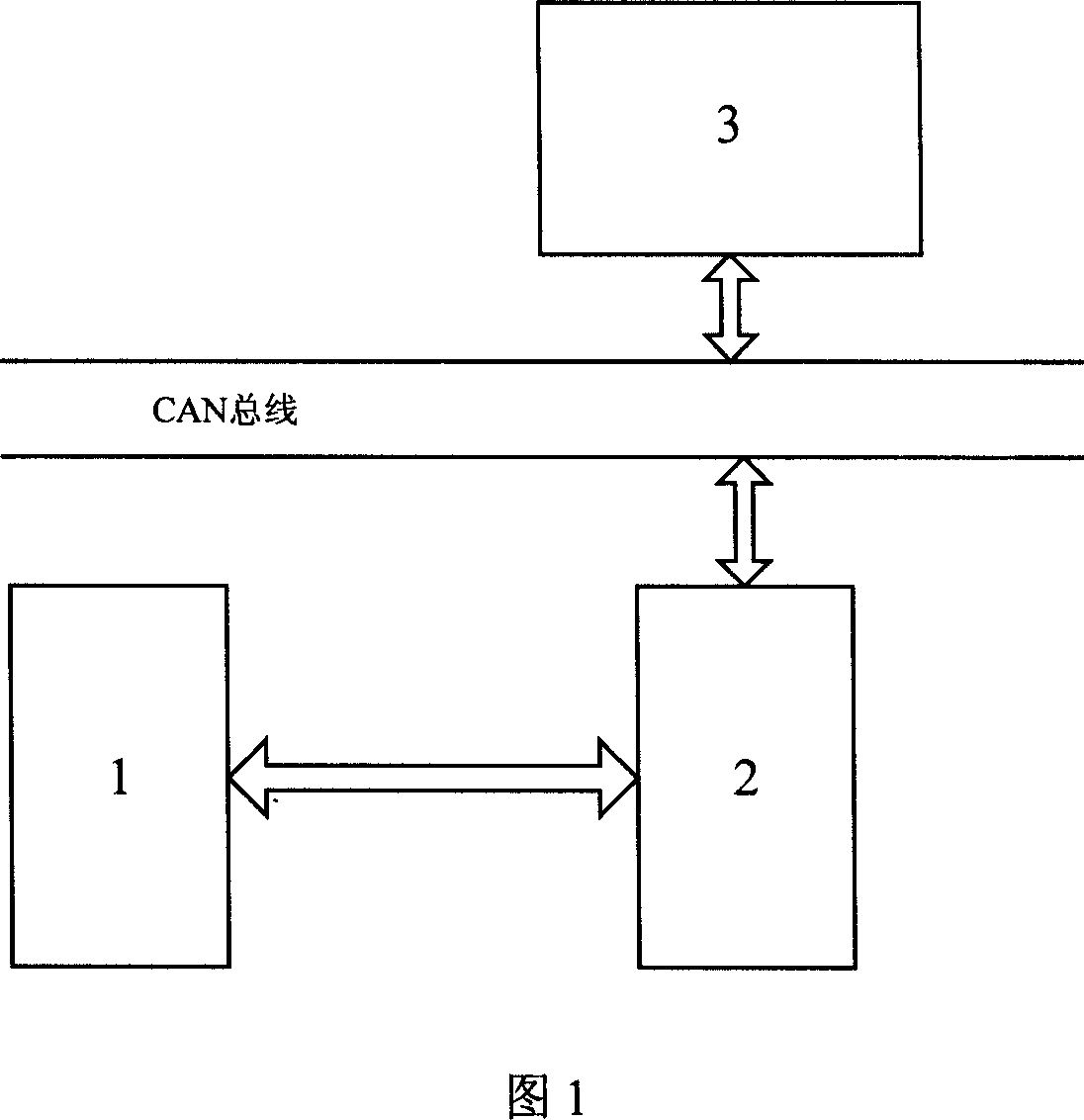
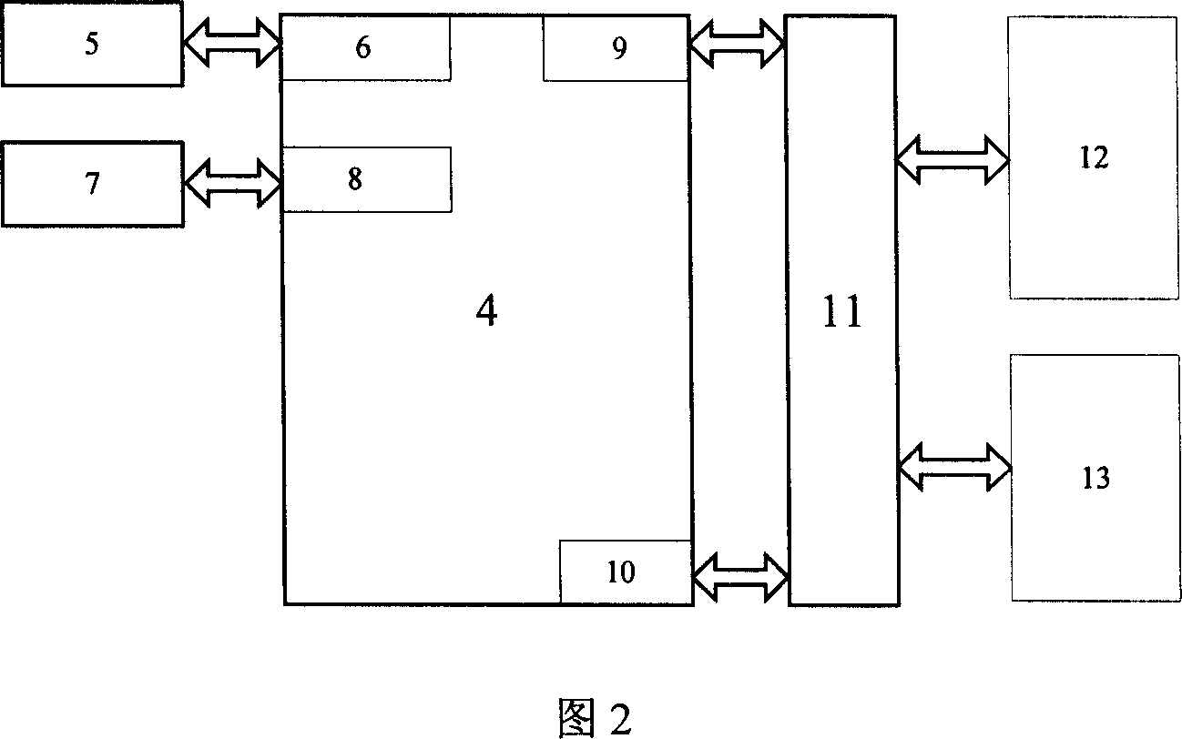
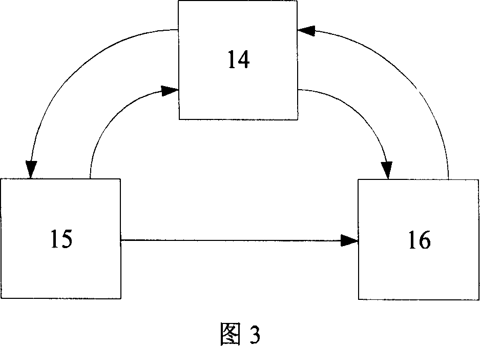

Image

  • Data sampling monitoring control device and method for micro combustion steam turbine
  • Data sampling monitoring control device and method for micro combustion steam turbine
  • Data sampling monitoring control device and method for micro combustion steam turbine

Examples


Embodiment Construction

[0128] A preferred embodiment of the present invention is shown in FIG. 7 to FIG. 24 .

[0129] In this example, the controller of the communication connection unit is selected as TMS320LF2407A, written in C language. Figure 7 is the circuit schematic diagram of the communication connection unit in this example, and Figure 7(a) is the circuit diagram of the power supply. The power supply uses the LM3940 voltage regulator to convert the 5V power supply into a 3.3V power supply to supply power to the controller. Figure 7(b) is a schematic diagram of the controller TMS320LF2407A and its peripheral circuits, the 25, 70, 26, and 72 pins of TMS320LF2407A are respectively connected to the 5 and 6 pins of IC21 in Figure 7(e), and the 5 and 6 tubes of IC19 The 2, 3, 5, 6, 17, 19 pins of IC4 are respectively connected to the 4, 5, 6, 7, 2, 3 pins of IC20 in Figure 7(f), and the 8 pins of IC4 are connected to IC5 18 pins of IC are connected with 18 pins of IC6, 20 pins of IC4 are connec...


PUM


Abstract

This invention relates to micro gas machine data collection monitor and control device and method, which comprises communication connection unit and upper machine, wherein, the connection unit is connected to the upper machine through CAN bus and gas control system; upper machine gas system control is to send order to memory data through communication and through CAN bus to each unit of the gas control system; the upper machine sends order and memory data to the communication module and function module.

Description

Technical field: [0001] The invention belongs to the field of information technology, and in particular relates to a micro-turbine data acquisition monitoring control device and method. Background technique: [0002] The development trend of micro gas turbine is high parameters, large capacity, high speed and complex operation system. Therefore, more stringent requirements are put forward for the operation level of micro gas turbines, which cannot be met only by operating personnel's experience and manual operation. Therefore, it is objectively required to have a monitoring system that can accurately and quickly respond to the operating state of the gas turbine. [0003] SCADA (Supervisory Control And Data Acquisition) system, that is, data acquisition and monitoring control system. The application fields of SCADA program products are very wide, and it can be applied to many fields such as data acquisition, monitoring control and process control in power system, water supp...

Claims


Application Information

Patent Timeline
Patent Type & Authority Applications(China)
IPC IPC(8): G05B19/418F02C9/00
CPCY02P90/02
Inventor 张化光李爱平闫士杰边春元陈宏志刘秀翀
Owner NORTHEASTERN UNIV
Learn More