

Abnormality diagnosis system for machinery
A technology for abnormal diagnosis and mechanical equipment, which is applied in the direction of mechanical bearing testing, measuring devices, instruments, etc., and can solve problems such as inability to identify abnormal vibrations, increasing the number of sensor settings, and the large number of input circuits and wiring of signal processing units, etc.
- Summary
- Abstract
- Description
- Claims
- Application Information
AI Technical Summary
Problems solved by technology
Method used
Image

Examples
no. 2 Embodiment
[0199] 9 is a block diagram showing a second embodiment of the abnormality diagnosis system of the present invention, and FIG. 10 is a block diagram showing an embodiment of a microcomputer (MPU) and its peripheral circuits which are specific components of the abnormality diagnosis system of the present invention.
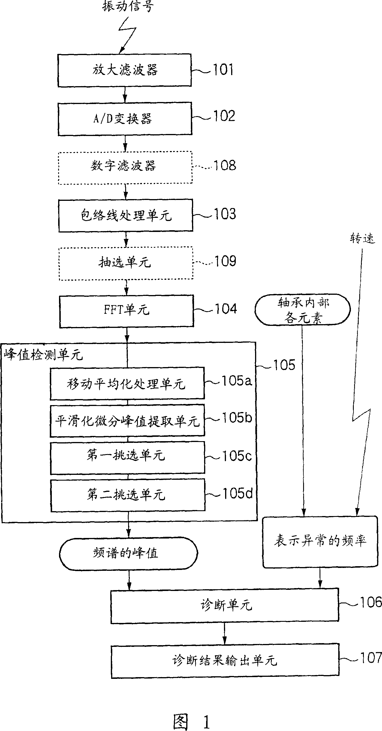
[0200] As shown in Figure 9, the abnormal diagnosis system of the present invention comprises: amplification filter (filter processing unit) 201, A / D converter 202, the first digital low-pass filter 203, the first extraction unit (extraction unit) 204 , an envelope processing unit 205, a second digital low-pass filter 206, a second sampling unit (extraction unit) 207, an FFT operation unit 208, a diagnosis unit 209, a speed conversion processing unit 210, and a diagnosis result output unit 211.
[0201] The amplification filter 101 receives a signal detected by a sensor (vibration sensor, acoustic sensor, etc.) that detects sound or vibration generated by a mechanic...
no. 3 Embodiment
[0218] Fig. 16 is a block diagram showing a third embodiment of the abnormality diagnosis system of the present invention. In the third embodiment, the digital low-pass filters 203 and 206 provided before and after the envelope processing unit 205 in the second embodiment and the decimation processing unit 204 before the envelope processing unit 205 are omitted. This configuration can be applied even if the S / N ratio is slightly lowered, as long as the frequency resolution of the envelope waveform analysis can be improved by FFT calculation with a small number of points.
[0219] The decimation process, which does not use a digital low-pass filter, suffers from aliasing and instead acts as a low-pass filter process itself. Furthermore, the result of the envelope processing itself also serves as the low-pass filter processing, so it is considered that the digital low-pass filter 206 before the decimation processing section 207 is omitted in many cases. If no aliasing is known ...
no. 4 Embodiment
[0223] Fig. 17 is a block diagram (hardware configuration diagram) showing a fourth embodiment of the abnormality diagnosis system of the present invention. 18 is a flowchart showing the flow of a series of processing in the abnormality diagnosis system of the fourth embodiment. A synchronous DRAM (SDRAM) 221 a , a flash memory 222 , an amplification filter (filter processing unit) 223 , and a liquid crystal display (LCD) 224 are connected to the microcomputer 220 .
[0224] Microcomputer 220 includes DSP220b and flash RAM220c in addition to CPU220a.
[0225] DSP220b has a built-in X / Y-RAM220e composed of X-RAM and Y-RAM connected by a dedicated bus, so that the product-sum operation can be executed with a dedicated command in one cycle. The capacities of the X-RAM and the Y-RAM are each 8 kilobytes. DSP220b plus the command bus can access three buses at the same time, and can execute multiple commands at the same time. X / Y-RAM is called dual-channel RAM, dual-arm access RA...
PUM
 Abstract
Description
Claims
Application Information