Magnetism-integrated double decompression semi-bridge converter

A half-bridge inverter and magnetic integration technology, which is applied in the direction of converting AC power input to DC power output, output power conversion devices, electrical components, etc., can solve the problem of the large volume and weight of double-buck half-bridge inverters and other issues, to achieve the effect of reducing volume and loss, improving efficiency, and reducing the size of the magnetic core

Inactive Publication Date: 2007-03-14
NANJING UNIV OF AERONAUTICS & ASTRONAUTICS
View PDF0 Cites 10 Cited by
  • Summary
  • Abstract
  • Description
  • Claims
  • Application Information

AI Technical Summary

Problems solved by technology

[0003] 1. Purpose of the invention: The purpose of the present invention is to provide a double-step-down half-bridge inverter that can solve the technical problems of the existing double-step-down half-bridge inverters with large volume and weight

Method used


Image

  • Magnetism-integrated double decompression semi-bridge converter
  • Magnetism-integrated double decompression semi-bridge converter
  • Magnetism-integrated double decompression semi-bridge converter

Examples


Embodiment 1

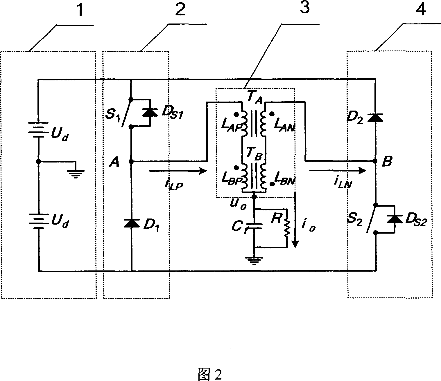
[0017] Embodiment 1: As shown in Figure 2, the magnetically integrated double-buck half-bridge inverter of this embodiment includes the first bridge arm 2 of the inverter, the second bridge arm 4 of the inverter, and also includes the magnetically integrated coupling Inductor 3, magnetically integrated coupling inductance 3 includes a first coupling filter inductance A and a second coupling filter inductance B, the series connection point of the first power switch tube S1 and the first freewheeling diode D1 in the first bridge arm 2 of the inverter is connected to the second The primary side LAP of a coupling filter inductor A is connected to the terminal with the same name. The end of the same name is connected; in the magnetic integrated coupling inductor 3, the primary side LAP of the first coupling filter inductor A and the primary side LBP of the second coupling filter inductor B are connected in series to form the primary side of the magnetic integrated coupling inductor ...

Embodiment 2

[0020] Embodiment 2: The structure of this embodiment is basically the same as that of Embodiment 1. The difference is that the structure of the magnetically integrated coupled inductor of this embodiment is shown in Figure 4 (b): in the primary side of the magnetically integrated coupled inductor 3, the first The opposite end of the primary side LAP of the coupling filter inductor A is connected to the opposite end of the primary side LBP of the second coupling filter inductor B; in the secondary side of the magnetically integrated coupling inductor 3, the secondary side LAN of the first coupling filter inductor A The opposite end is connected with the same end of the secondary side LBN of the second coupling filter inductor B.

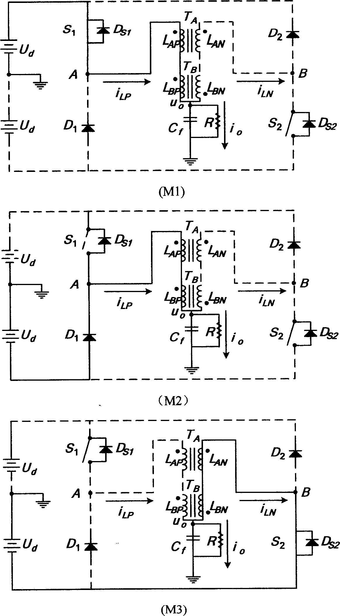
[0021] As shown in Figure 3, the first bridge arm voltage UA output voltage +Ud of the first bridge arm voltage UA output voltage +Ud of the magnetically integrated double-buck half-bridge inverter in the non-bias current half-cycle operation mode in ...


PUM


Abstract

This invention provides one magnetic double lowering semi-bridge inverter, which comprises inverter first arm, second arm, and magnetic couple induction composed of first and second couple filter induction. This invention adopts magnetic integration technique to roll magnetic parts into one common core through couple means and parameters setting to reduce parts volume and consumption.

Description

1. Technical field [0001] The invention relates to an inverter, in particular to a double step-down half-bridge inverter. 2. Background technology [0002] With the development of power electronics technology, the power supply is developing in the direction of smaller volume, higher efficiency and higher power density. Existing studies have shown that the volume weight and loss of magnetic components in switching power supplies account for a considerable proportion. According to statistics, the weight of the magnetic parts generally accounts for 20-30% of the total weight of the converter, and this proportion will further increase with the increase of the switching frequency. In order to reduce the volume and weight of switching power supplies and increase the power density, it is necessary to conduct research on related technologies for reducing the volume, weight and loss of magnetic parts. The structure of the traditional double-buck half-bridge inverter is shown in Fig...

Claims


Application Information

Patent Timeline
Patent Type & Authority Applications(China)
IPC IPC(8): H02M7/515
Inventor 洪峰单任仲王慧贞严仰光
Owner NANJING UNIV OF AERONAUTICS & ASTRONAUTICS
Why Eureka
Try Eureka