Bladder-free quick-heating drinking water machine
A rapid heating and water dispenser technology, applied in water heaters, fluid heaters, lighting and heating equipment, etc., can solve the problems of easy scaling, waste of electric energy, short service life of electric heating tubes, etc. The effect of saving electricity and high heating efficiency
- Summary
- Abstract
- Description
- Claims
- Application Information
AI Technical Summary
Problems solved by technology
Method used
Image
Examples
Embodiment 1
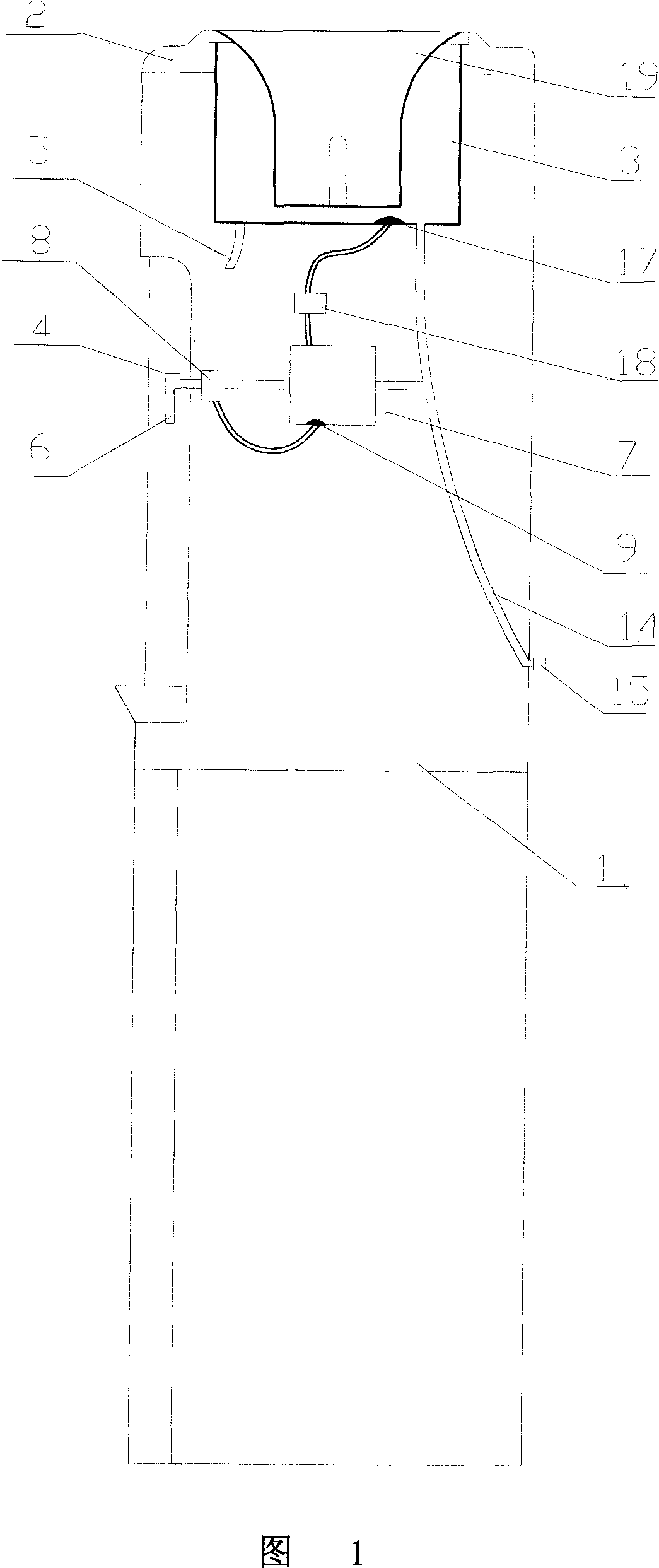
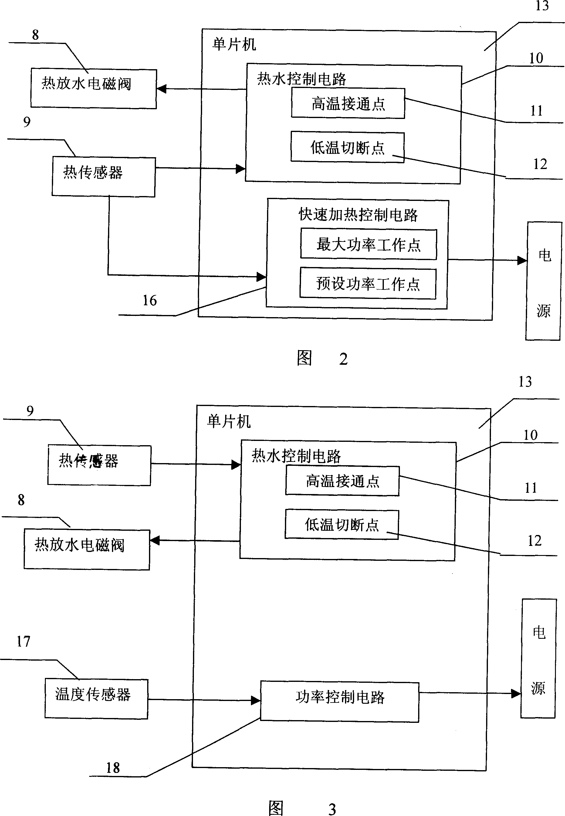
[0025] Referring to Fig. 1, Fig. 2, Fig. 5 and Fig. 6, a quick heating water dispenser without a heat tank includes a housing 1, a bottle base 2, a bucket 3 located on the bottle base 2, a power switch 4 and a cold water outlet 5, The hot water outlet 6 and the cold water outlet 5 are connected to the water bucket 3 through the cold water pipe. The water bucket 3 is equipped with a smart core, and a cold water valve is installed on the cold water pipe. The rapid heater 7 of the temperature, the water inlet of the rapid heater 7 communicates with the water bucket 6, the water outlet of the rapid heater 7 communicates with the hot water outlet 6 through the heat discharge solenoid valve 8, and the electric heating tube of the rapid heater 7 passes through the power switch 4 Connect to an external power supply, the power switch 4 is set on the hot water outlet 6; a thermal sensor 9 is provided in the rapid heater 7, and the thermal sensor 9 is electrically connected to the input e...
Embodiment 2
[0029] Referring to Fig. 1, Fig. 2, Fig. 5, and Fig. 6, the external power supply described in this embodiment is a power supply with adjustable power; the housing 1 also includes a power supply for the maximum power (2000w) operation of the electric heating tube when the heater is started. 1. The rapid heating control circuit 16 that runs according to the preset power (1500w) when the heat discharge solenoid valve is turned on, the rapid heating control circuit 16 includes a maximum power operating point and a preset power operating point; the input of the preset power operating point terminal is electrically connected to the thermal sensor 9, and the output terminal of the rapid heating control circuit 16 is connected to the power supply. The fast heating control circuit 16 is also integrated on the single-chip microcomputer 13 .
[0030] Turn on the power switch 4, the electric heating tube runs at the maximum power (2000w), and heats the cold water quickly. When the temper...
Embodiment 3
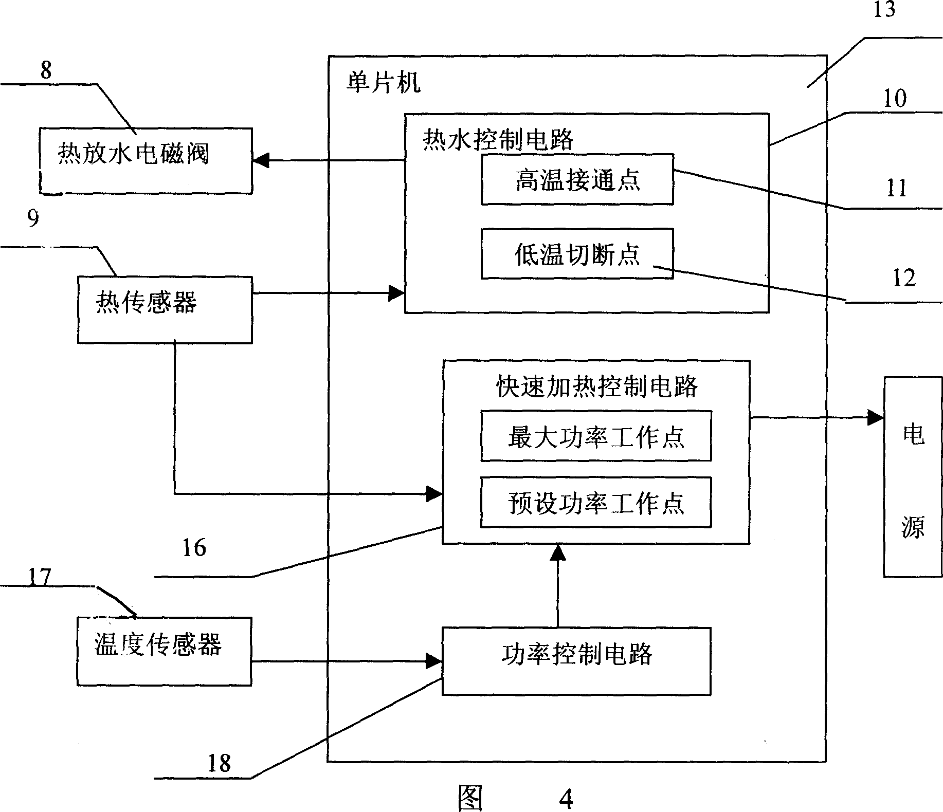
[0033] Referring to Fig. 1, Fig. 3, Fig. 5 and Fig. 7, a temperature sensor 17 is provided on the water bucket 3 of the present embodiment, and the external power supply is a power supply with adjustable power; The temperature level controls the power control circuit 18 of the preset power of the electric heating tube, and the temperature sensor 17 is electrically connected to the input end of the power control circuit 18; the output end of the power control circuit 19 is connected to the power supply. The power control circuit 18 is also integrated on the single chip microcomputer 13 .
[0034] The power control circuit 18 can control the different powers of the electric heating tubes according to the different temperatures of the water bucket 3. For example, in summer, the water temperature in the water bucket is high, and the power of the electric heating tube is relatively low; in winter, the water temperature in the water bucket is low, and the electric heating tube The p...
PUM
 Abstract
Description
Claims
Application Information
 - R&D
- Intellectual Property
- Life Sciences
- Materials
- Tech Scout
- Unparalleled Data Quality
- Higher Quality Content
- 60% Fewer Hallucinations
Browse by: Latest US Patents, China's latest patents, Technical Efficacy Thesaurus, Application Domain, Technology Topic, Popular Technical Reports.
© 2025 PatSnap. All rights reserved.Legal|Privacy policy|Modern Slavery Act Transparency Statement|Sitemap|About US| Contact US: help@patsnap.com


