
Box-type section beam-column node structure and welding method

A beam-column joint and box-column technology, which is applied in building construction, construction, etc., can solve the problems of reducing material cost and production cost, difficult to guarantee, and difficult to achieve quality, and achieves reduction of material cost and production cost, integrity Strong, Reliable Effects

Inactive Publication Date: 2007-03-28
北京三杰国际钢结构有限公司
View PDF0 Cites 26 Cited by
  • Summary
  • Abstract
  • Description
  • Claims
  • Application Information

AI Technical Summary

Problems solved by technology

[0004] The purpose of the present invention is to propose a box-section beam-column joint structure and its welding method, which solves the difficult problems of electroslag welding of the inner diaphragm of the joint when the inner diaphragm of the box-shaped steel column is thicker, and the quality is difficult to guarantee. The invention also reduces material and production costs by using two medium-thick partitions instead of one extra-thick partition

Method used


Image

  • Box-type section beam-column node structure and welding method
  • Box-type section beam-column node structure and welding method
  • Box-type section beam-column node structure and welding method

Examples


Embodiment 1

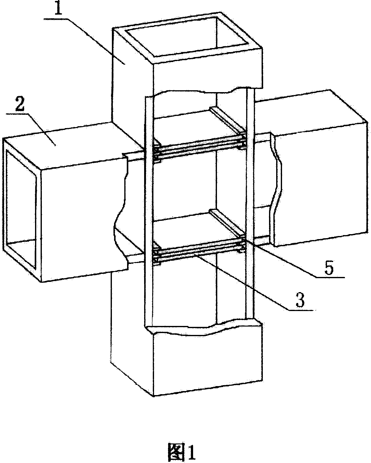
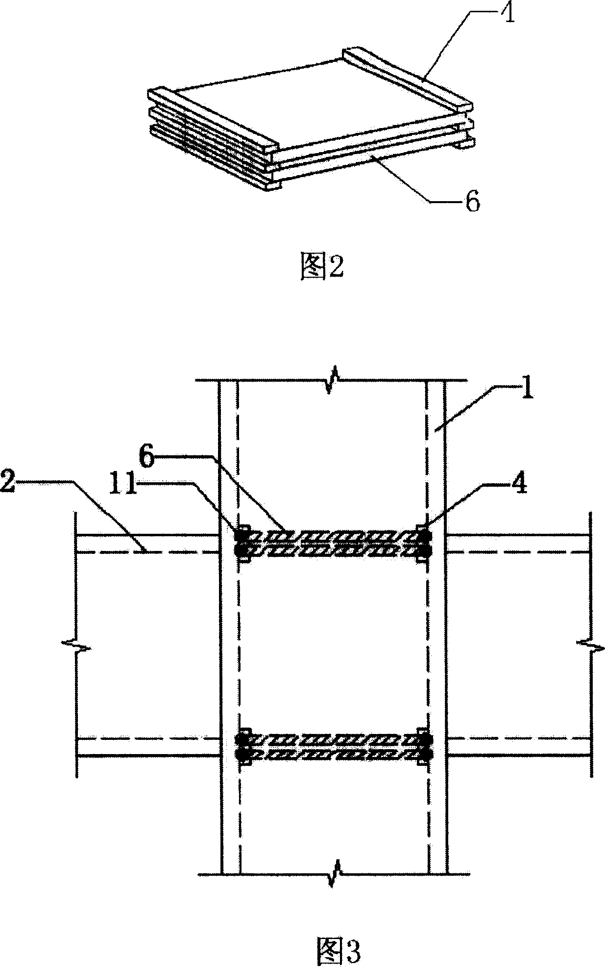
[0038] The first embodiment is shown in Figures 1 to 3. This box-section beam-column joint structure is formed by cross-welding box-shaped steel columns 1 and box-shaped steel beams 2, and a transverse stiffening inner partition 3 is welded in the box-shaped steel columns. The above-mentioned stiffening inner partition 3 is composed of two horizontal steel plates 6 with the same shape and size as the inner section of the box-shaped column and three steel spacers 4 sandwiched between the horizontal steel plates and located at both ends of the horizontal steel plates. The two ends of each horizontal steel plate are 5 away from the electroslag welding welding gap between the box-shaped steel wall plates, and the welding gap is welded by electroslag welding penetration, so that the stiffened inner partition 3 is welded to the box-shaped steel column 1 into one. The total thickness of the above two horizontal steel plates is greater than or equal to the thickness of the flange of t...

Embodiment 1

[0039] The concrete steps of implementing the welding of Example 1 are as follows:

[0040] Step 1: Two horizontal steel plates 6 with the same shape and size as the inner section of the box-shaped steel column 1 and three steel spacers 4 are interlaced and spot-welded to form a stiffened inner partition 3, and the space between each two steel spacers 4 and the horizontal A strip-shaped reserved electroslag welding gap 5 is formed between the ends of both sides of the steel plate 6 and the wall plate of the box-shaped steel column.

[0041] Step 2: Referring to Fig. 5, spot-weld the assembled stiffening inner partition 3 on the lower flange plate 8 of the box-shaped steel column at a predetermined position.

[0042] Step 3: Referring to Figure 6, weld the box-shaped steel column webs 9 on both sides of the box-shaped steel column to the lower flange plate 8 of the box-shaped steel column to form a box-shaped column with one side temporarily open, and then place the stiffened i...

Embodiment 2

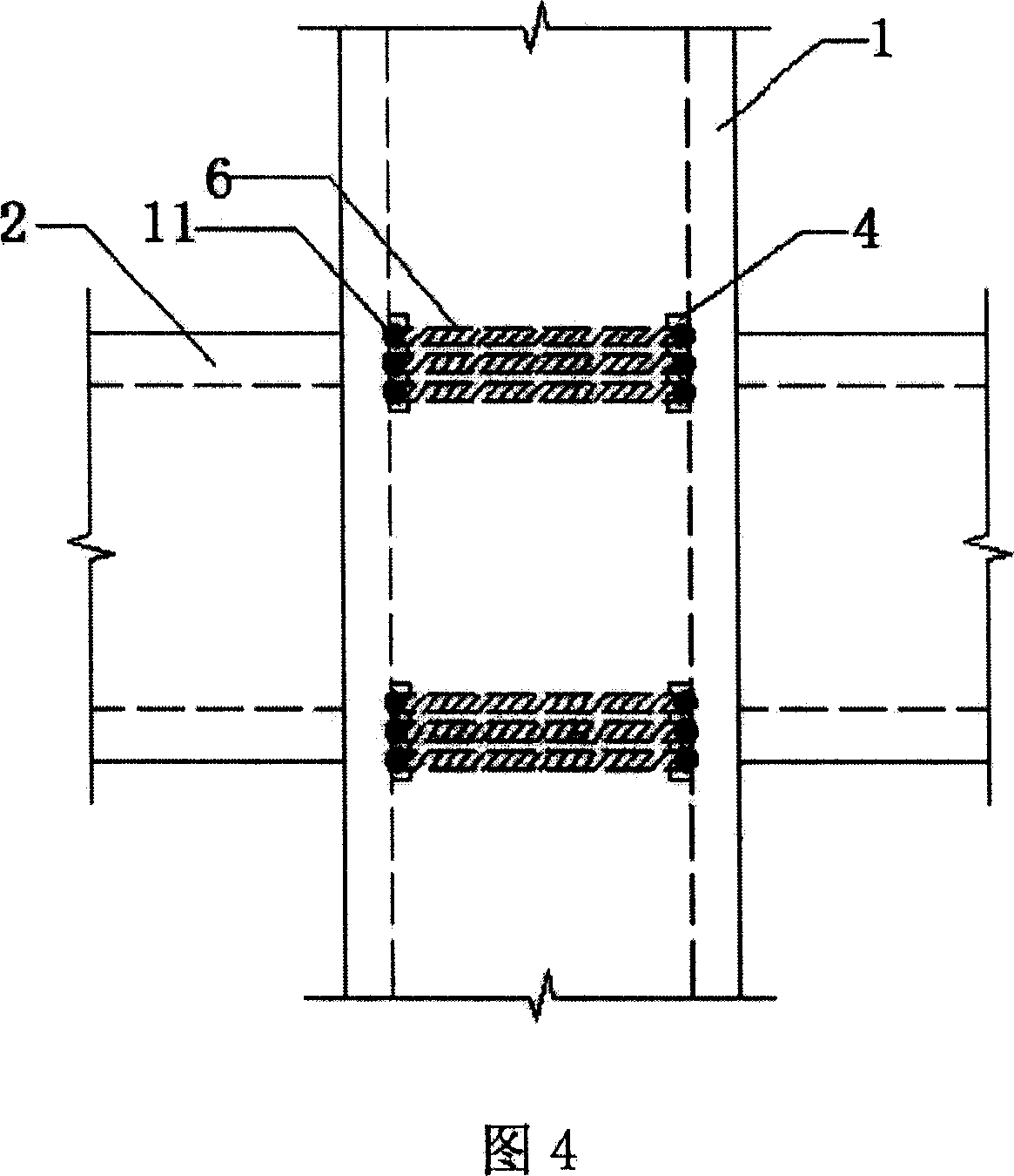
[0048] Implementation example two is shown in Fig. 4, the stiffening inner partition 3 is divided into three horizontal steel plates 6, and four steel pads 4 are used.

[0049] The welding concrete steps of implementation example two are as follows:

[0050] Step 1: Three horizontal steel plates 6 with the same internal section as the box-shaped steel column 1 and four steel pads 4 are interlaced and spot-welded to form a stiffened inner partition 3, and the space between each two steel pads 4 is connected to the horizontal steel plate 6 A strip-shaped reserved electroslag welding welding gap 5 is formed between the ends on both sides of the box-shaped column steel wall.

[0051] Step 2: spot-weld the assembled stiffening inner partition 3 on the lower flange plate 8 of the box-shaped steel column at a predetermined position.

[0052] Step 3: Weld the box-shaped steel column web 9 on both sides of the box-shaped steel column with the lower flange 8 of the box-shaped steel col...


PUM


Abstract

The invention relates to a box section beam column node structure and sintering method that is sintered from box steel column and girder steel. Enforcing internal partition board is set in the steel column. Two sides of each horizontal steel board sinter clearance between steel column board and make the enhanced internal partition board with steel column to integrity. The total thickness of the two or three boards of horizontal steel boards matches to the external steel girder steel flange thickness that always larger or equal to the thickness of external steel girder steel flange. The invention ensures the sintering quality and saves producing cost.

Description

Technical field: [0001] The invention relates to a building steel structure node structure and a processing method thereof. Background technique: [0002] In recent years, domestic high-rise steel structure buildings have been increasing, and more and more columns are box-shaped. Larger box-shaped steel columns are generally welded by four steel plates, and rigid connections are often used between beams and columns. In order to ensure the continuous transmission of internal forces between the steel beams connected to the columns, internal partitions are generally installed in the box-shaped steel columns at positions corresponding to the planes of the upper and lower flanges of the beams. It is also required that the inner partition is of the same thickness as the beam flange plate and welded with full penetration on all four sides of the inner wall of the column. During manufacture, the inner partition can be welded to the two wall panels of the box column first, and the c...

Claims


Application Information

Patent Timeline
IPC IPC(8): E04B1/19E04B1/24E04B1/58
Inventor 郭海山束伟农李黎明
Owner 北京三杰国际钢结构有限公司
Features
  • Generate Ideas
  • Intellectual Property
  • Life Sciences
  • Materials
  • Tech Scout
  • Unparalleled Data Quality
  • Higher Quality Content
  • 60% Fewer Hallucinations
Learn More