
Screan cursor movement control method and cursor movement controller

A controller and screen light technology, applied in the field of screen cursor movement control and cursor movement controller, can solve the problems of short movement distance, increased fatigue of operator's hand and arm joints, limited application scope, etc. The effect of improving the convenience of use, reducing the amount of hand movement, and convenient and flexible operation

Inactive Publication Date: 2007-03-28
LENOVO (BEIJING) LTD
View PDF1 Cites 9 Cited by
  • Summary
  • Abstract
  • Description
  • Claims
  • Application Information

AI Technical Summary

Problems solved by technology

But this method is not easy to master in use, especially the jumping time between two fingers is not easy to master, which makes it difficult to succeed when the cursor moves greatly, and the application range is limited to the touchpad
[0005] The existing technology ALPS company realizes on the touch panel to determine the moving distance according to the moving speed of the finger on the touch panel, but there are also problems, such as the speed is not easy to grasp, the speed is too slow, the single cursor moving distance is short, and the finger If you move too fast, the touchpad will not sense it and refuse to move the cursor. According to calculations, the furthest distance you can move the cursor from the touchpad at one time is about one and a half monitors. This method is especially limited when there are multiple monitors
[0006] In the prior art, IBM Corporation determines the moving distance of the cursor on the touch stick according to the force of the finger on the touch stick, but the application of this technology has certain limitations: for example, the moving speed of the finger and the pressure of the finger are different. Difficult to control, and the constant force of the fingers will increase the fatigue of the operator
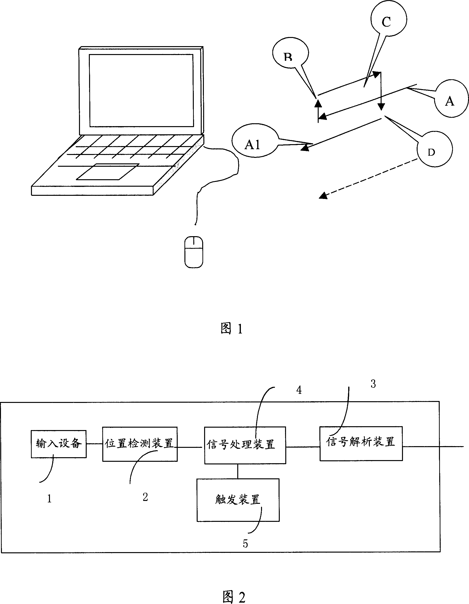
[0007] At present, cursor movement controllers such as mouse and touchpad, when the operator needs to move the cursor on the screen for a relatively long distance, as shown in Figure 1, if the cursor on the screen can be moved from right to Sitting down and moving, the operator goes through the route from A to B to C to D as shown in the figure to reach A1, then only step A and A1 have direct contributions to moving the cursor on the screen, while steps B, C and D are useless , are all preparations for the movement of A1, and the useless work of steps B, C, and D increases the fatigue of the operator's hand and arm joints

Method used


Image

  • Screan cursor movement control method and cursor movement controller
  • Screan cursor movement control method and cursor movement controller
  • Screan cursor movement control method and cursor movement controller

Examples


no. 1 example

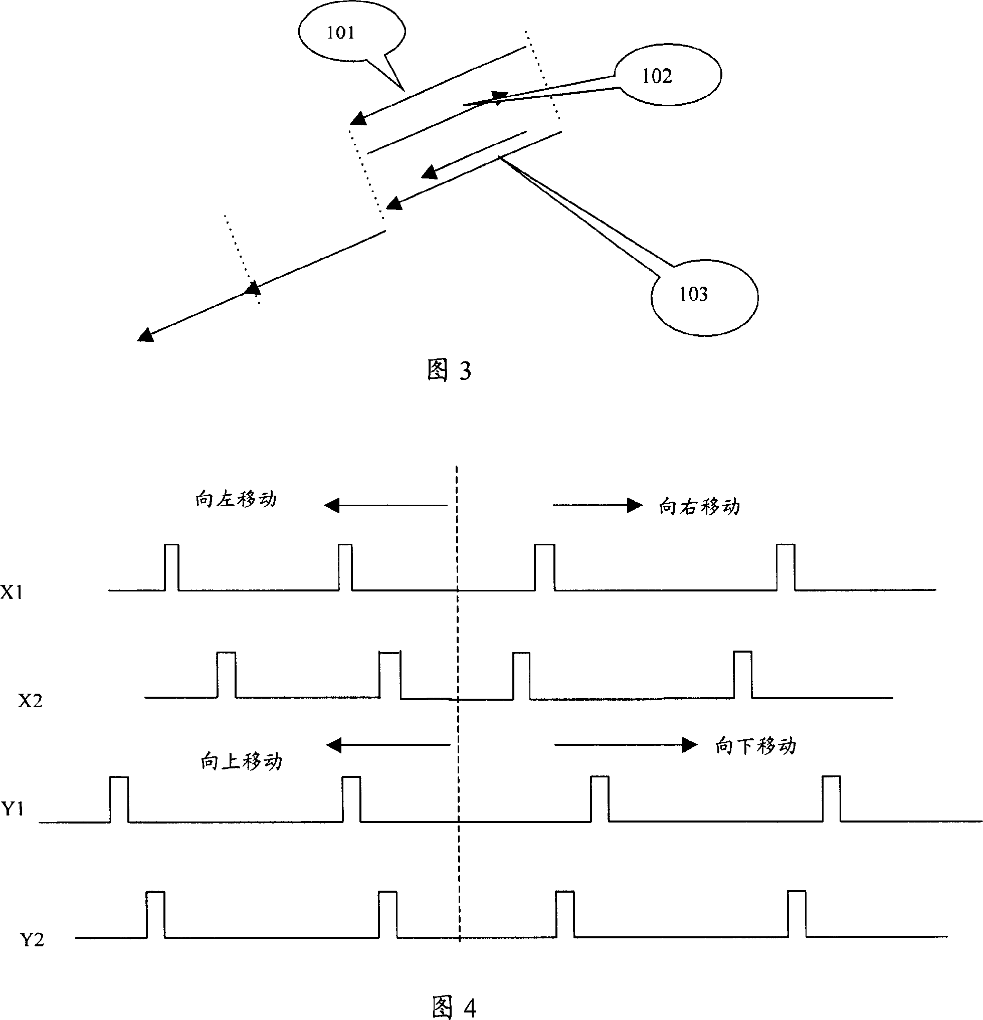
[0050] The first embodiment: the optical mechanical mouse is driven by two positioning axes arranged at 90 degrees by the rubber roller ball at the bottom of the mouse. The two ends of the positioning shaft are connected with circular optical encoders. The optical encoder of the optical mechanical mouse consists of a disc with many slits, and photoelectric cells and light-emitting diodes on both sides. When the mouse moves on the desktop, the rubber ball drives the disc on the optical encoder to rotate, and the photoelectric tube receives intermittent signals. The position detection device in this embodiment is a photosensitive chip. If the optical signal is received, the photosensitive chip A "1" signal will be generated, and if no optical signal is received, it will be set as a signal "0". The optical codes on the X and Y axes are composed of two pulse signals that are not on the diameter line. As shown in Figure 4, when the phase of X1 is earlier than that of X2, it is con...

no. 2 example

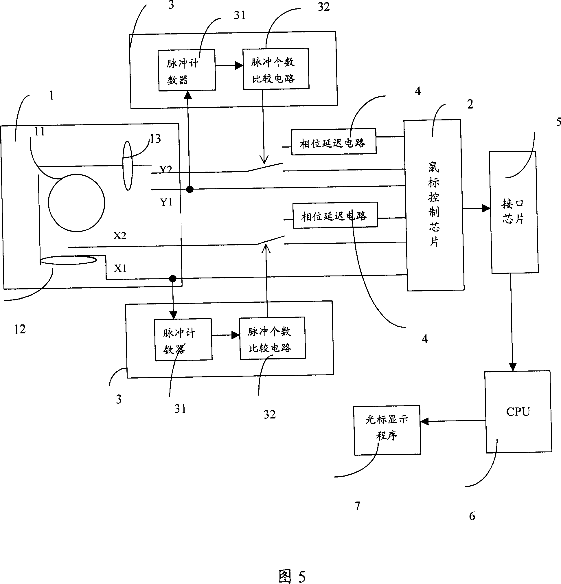
[0053] The second embodiment: In this embodiment, the optical-mechanical mouse is still used as an example. The difference is that in this embodiment, the signal processing device is a pulse switch connected to each branch of the X and Y axes, and the trigger device consists of The control device controls its working state.

[0054] FIG. 6 is a schematic block diagram of the optical mechanical mouse. In the figure, a pulse switch 4 is set in one of the pulse signals on the X and Y positioning axes, as the signal processing device described in the present invention, when the trigger device 3 triggers the motion track of the present invention, the reverse pulse signal is cut off .

[0055] In this embodiment, a control device 8 is also included, and the control device 8 can add function keys on the mouse, or realize by setting hotkeys or combination keys on the keyboard. When the control device 8 is pressed, the signal connected to the control device 8 The wire sends a control...

no. 3 example

[0056] The third embodiment: generally there are two integrated circuits in the current optical mouse, one is a CMOS / DSP chip, and the other is an interface conversion chip of USB / PS2, and the CMOS / DSP chip includes three parts: image capture module, DSP image Analysis module, X, Y direction relative displacement pulse output module. The DSP image analysis module chip is the position detection device in this embodiment. The interface chip actually counts and processes the pulse signals generated by CMOS / DSP, and then converts them into USB / PS2 signal output. The PS2 signal output processes the pulse signal through the interface chip and triggers it through the trigger device. Similarly, the trigger device can be triggered by detecting the speed or adding a mouse button. When it is detected that the corresponding button is pressed, the pulse signal processing device in the interface chip can process all the received pulse signals in the same direction, and then send a USB signa...


PUM


Abstract

This invention discloses a cursor location controller which consists of input device which was used to identify the input action and generate input signal; location checking device which was used to measure signal location change and generate impulse signal; signal analyzing device which was used to receive the impulse signal and analyze and switch it to a displace signal; signal disposal device which connects with the above two devices; a triggering device which connects to the disposal device, was used to control the working status. The advantages are as follows: the movement of operator's ankle was reduced; operating of control device on a narrow desk becomes more convenient.

Description

technical field [0001] The invention relates to the field of accessory equipment developed by PC hardware system components, in particular to a technology for controlling screen cursor movement, especially a control method for screen cursor movement and a cursor movement controller. Background technique [0002] The current PC systems all have human-computer interaction external devices to control the movement and clicking of the screen cursor. Usually, the PC system uses a cursor position controller to control the movement of the cursor. The current cursor position controller includes a position detection device and a signal analysis device, the position detection device detects the position change of the input signal of human-computer interaction, and generates various pulse signals; the signal analysis device receives the pulse signal and converts the pulse signal Analyze and convert it into a displacement signal, and then send it to the cursor display module in the host ...

Claims


Application Information

Patent Timeline
Patent Type & Authority Applications(China)
IPC IPC(8): G06F3/033G06F3/0354
Inventor 徐晓靖李众庆
Owner LENOVO (BEIJING) LTD
Learn More