Check patentability & draft patents in minutes with Patsnap Eureka AI!

Electrowetting display element

A technology for display components and components, applied in optical components, identification devices, nanotechnology for materials and surface science, etc., can solve the problems of complex manufacturing methods and difficulty in meeting the requirements of large pixel areas, and achieve simple manufacturing, Ease of addressing and driving effects

Inactive Publication Date: 2007-03-28
EASTMAN KODAK CO
View PDF5 Cites 1 Cited by
  • Summary
  • Abstract
  • Description
  • Claims
  • Application Information

AI Technical Summary

Problems solved by technology

Therefore, the existing methods are not easy to meet the requirements of large pixel area
In addition, the structure of the existing method requires microfabrication, so the manufacturing method is relatively complicated

Method used


Image

  • Electrowetting display element
  • Electrowetting display element
  • Electrowetting display element

Examples


Embodiment Construction

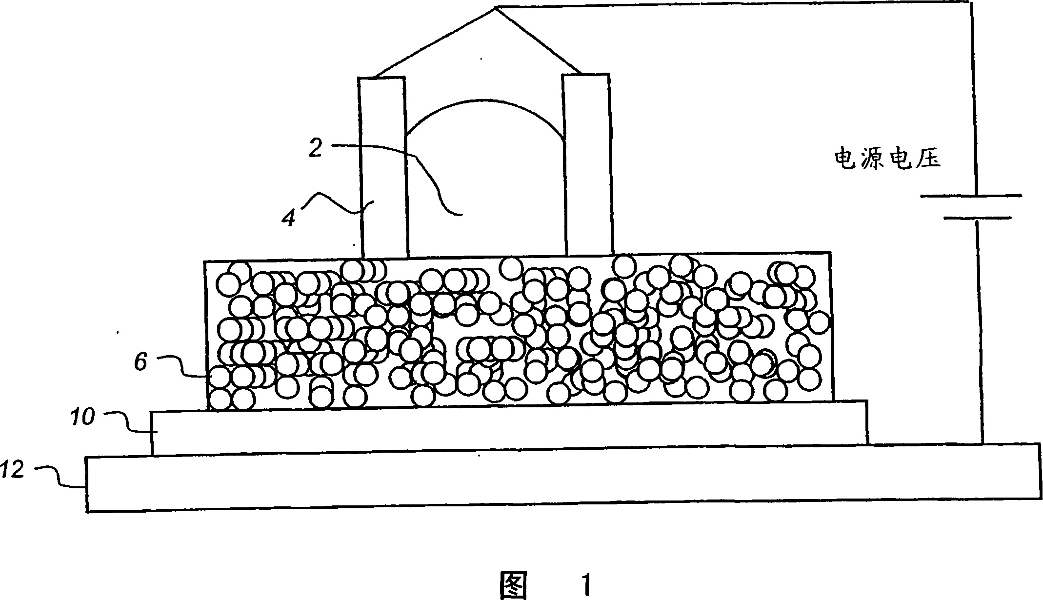
[0016] Fig. 1 is a schematic diagram of a single-layer display element 1 according to the invention. The invention relates to passive display elements.

[0017] Throughout the specification and claims, the word "above" means that an element is seen from that side. Use of the term "above" is not meant to limit the orientation of elements of the invention.

[0018] The element is based on a single-layer porous system. The element 1 comprises a hydrophobic porous layer 8 on which droplets of an electrically conductive liquid 2 are placed. The elements are preferably colored. This includes white liquid. The liquid becomes colored when dyes or pigments are added. Adding ions to a solution creates a conductive liquid. The conductive liquid may also be an ionic liquid.

[0019] Electrodes 4 pin the droplet in position on top of hydrophobic layer 8 . The contact angle of the liquid with the electrodes is preferably less than 90°. Below the porous layer 8 a dielectric layer 10...


PUM


Abstract

A display element comprising a single layer of porous material, a discrete drop of liquid and means for connecting a voltage supply to the layer, the layer comprising a plurality of conductive particles covered with a lyophobic and electrically insulating covering, whereby on application of a voltage between the liquid and the layer the drop of liquid moves into the layer, the drop moving back out the layer upon removal of the voltage, the movement of the liquid effecting an optical change when viewed from above the porous layer.

Description

technical field [0001] The invention relates to the field of display elements, in particular passive display elements. Background technique [0002] Many companies are actively looking for display components that are easy to manufacture. These display elements can be active, that is, emit light, such as LED, OLED, PLED, EL, etc., or passive, that is, affect the passage, reflection, or refraction of light, such as LCD, CLC, electronic ink, etc. Some passive systems are bistable, that is, they can switch and remain switched when power is removed. Most of the previously known structures are easily made to be colored. [0003] Various electrowetting display elements are previously known. [0004] US6473492 describes a fluid element arrangement for rearranging fluid within a capillary. A voltage is used to move the fluid in the capillary to the required height. US2002 / 0080920 describes a filter arrangement using an array of elements according to US6473492 for an X-ray imagin...

Claims


Application Information

Patent Timeline
Patent Type & Authority Applications(China)
IPC IPC(8): G02B26/02G09F9/37
CPCG02B26/004B82Y30/00
Inventor E·维法雷A·克拉克
Owner EASTMAN KODAK CO
Features
  • R&D
  • Intellectual Property
  • Life Sciences
  • Materials
  • Tech Scout
  • Unparalleled Data Quality
  • Higher Quality Content
  • 60% Fewer Hallucinations
Learn More