Device for fusing injection needle

An injection needle and fusing technology, which is applied in hypodermic injection devices, needles, medical science and other directions, can solve the problems of reduced use efficiency of electrode rollers, refractory damage and adhesion, and increased processing costs, so as to reduce processing costs and save money. effect of time

Inactive Publication Date: 2007-04-04
SEIWA PRO CO LTD +1
View PDF1 Cites 1 Cited by
  • Summary
  • Abstract
  • Description
  • Claims
  • Application Information

AI Technical Summary

Problems solved by technology

[0013] However, in order to make the current flow stably through the injection needle and prevent the above-mentioned melting loss and sticking, titanium, tungsten, and materials containing copper or silver (brass and phosphor bronze) with low resistance, high melting point, and high thermal conductivity are used. etc.) to form the electrode roller with a high-priced metal material such as an alloy, and in order to make the electrode roller contact with the electrical contact for energizing the electrode roller and improve the heat dissipation, it is formed as the injection needle fuse device of the above-mentioned prior art The structure in which the injection needle is extended in the axial direction so that the injection needle contacts the same position of the electrode roller can only use a part of the electrode roller, and the processing cost becomes high. In addition, the use efficiency of the electrode roller is reduced, so it is not preferable.
[0014] Furthermore, when the exchange efficiency of the electrode roller is high, the exchange time is required, and there is a problem that the treatment of the injection needle cannot be effectively performed.

Method used


Image

  • Device for fusing injection needle
  • Device for fusing injection needle
  • Device for fusing injection needle

Examples


Embodiment Construction

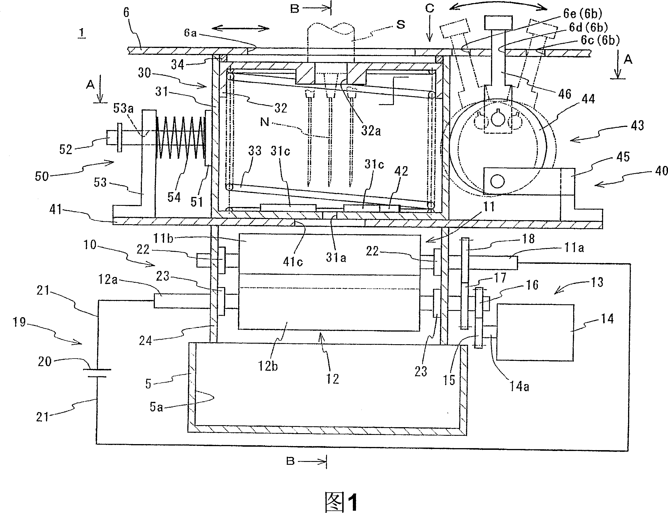
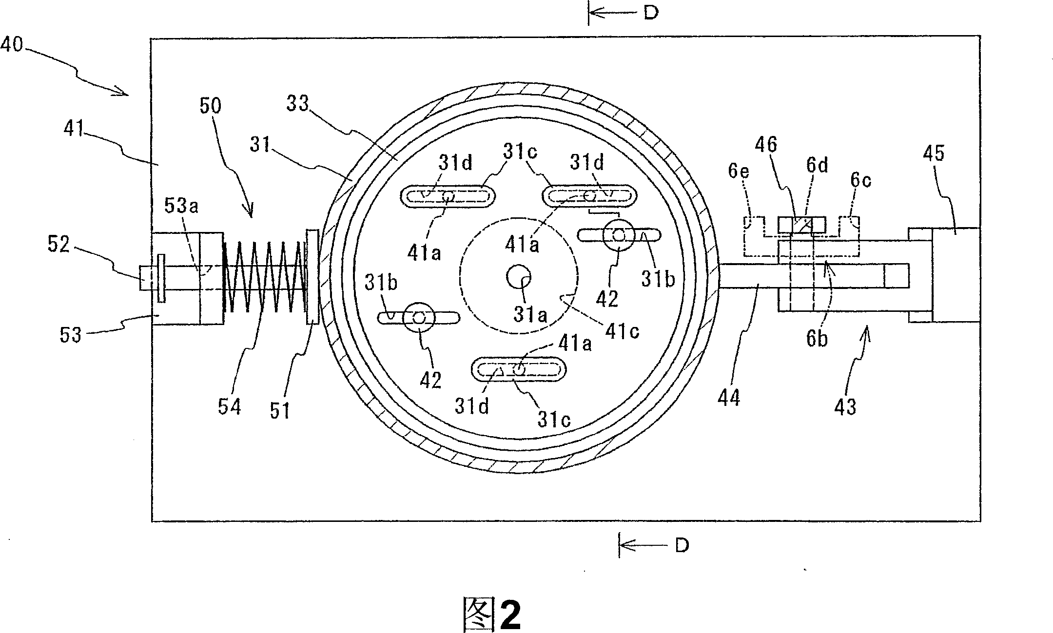
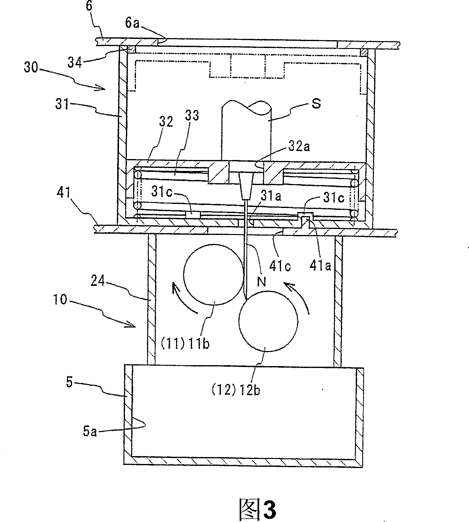
[0039] Hereinafter, the present invention will be described in detail with reference to the accompanying drawings. Among them, Fig. 1 is a cross-sectional view showing a schematic structure of an injection needle fuse device according to an embodiment of the present invention, Fig. 2 is a cross-sectional view in the direction of A-A indicated by an arrow in Fig. 1 , and Fig. 3 is a cross-sectional view indicated by an arrow in Fig. 1 . A cross-sectional view in the B-B direction is shown. In addition, FIG. 4 is a plan view in the direction C indicated by the arrow in FIG. 1 , and FIG. 5 is a cross-sectional view in the direction D-D indicated by the arrow in FIG. 2 .

[0040]As shown in Figures 1 to 5, the injection needle fusing device 1 of the present embodiment includes: a fusing mechanism 10 for fusing the injection needle N of the syringe S; a guide mechanism 30 for guiding the injection needle N to the fusing mechanism 10; adjusting the fusing mechanism 10 and The posit...


PUM


Abstract

A device for fusing an injection needle in which the treatment cost can be reduced by prolonging the lifetime of electrode rollers. The device (1) for fusing an injection needle comprises a fusing mechanism section (10) including two electrode rollers (11, 12) which can be brought into contact with the injection needle (N) of a syringe (S), a rotation drive mechanism (13) for rotating the electrode rollers (11, 12), and a power application mechanism (19) for applying power between the electrode rollers (11, 12), a guide mechanism section (30) including a holding member (32) for holding the syringe (S) and a guide member (31) which engages with the holding member (32), guides it toward the electrode rollers (11, 12), and then brings the injection needle (N) of the syringe (S) into contact with the electrode rollers (11, 12), and a position adjusting section (40) for adjusting the relative positional relation between the fusing mechanism section (10) and the guide mechanism section (30) in the axial direction of the electrode rollers (11, 12) and shifting the position where the injection needle (N) of the syringe (S) is brought into contact with the electrode rollers (11, 12).

Description

technical field [0001] The invention relates to an injection needle fusing device, which is used for fusing and discarding the injection needles of used syringes. Background technique [0002] For the used syringe, if the worker who handles it accidentally touches the injection needle, it is likely to cause secondary infection. Therefore, in recent years, an injection needle fuse device for fusing and discarding the injection needle has been proposed as such an injection needle. As a fuse device, for example, a device disclosed in Japanese Patent Application Laid-Open No. 11-285531 is known. [0003] The injection needle fusing device is composed of a fusing mechanism for fusing the injection needle of the syringe, a guide mechanism arranged above the fusing mechanism, and guiding the injection needle to the fusing mechanism. [0004] The above-mentioned fusing mechanism includes: two paired electrode rollers arranged in parallel and horizontally at intervals and in contact...

Claims


Application Information

Patent Timeline
Patent Type & Authority Applications(China)
IPC IPC(8): A61G12/00A61M5/32
CPCA61M5/3278A61M2005/3283
Inventor 伊东资哲奥田正明
Owner SEIWA PRO CO LTD
Why Eureka
Try Eureka