Consumable electrode arc-welding machine

A technology for arc welding machines and consumable electrodes, which is applied to arc welding equipment, welding equipment, electrical components, etc., and can solve problems such as arc instability, uncontrollability, and droplet hypertrophy

Active Publication Date: 2007-04-04
PANASONIC CORP
View PDF1 Cites 10 Cited by
  • Summary
  • Abstract
  • Description
  • Claims
  • Application Information

AI Technical Summary

Problems solved by technology

However, in the conventional control method, the voltage control during the arc period and the current control during the short circuit period cannot be controlled due to factors such as the occurrence of a micro-short circuit during welding and the enlargement of the droplet at the tip of the wire during the arc period.
Therefore, the conventional control method is accompanied by the instability of the arc or the occurrence of sputtering, or the generation of unstable factors in welding such as arc interruption.

Method used


Image

  • Consumable electrode arc-welding machine
  • Consumable electrode arc-welding machine
  • Consumable electrode arc-welding machine

Examples


Embodiment approach 1

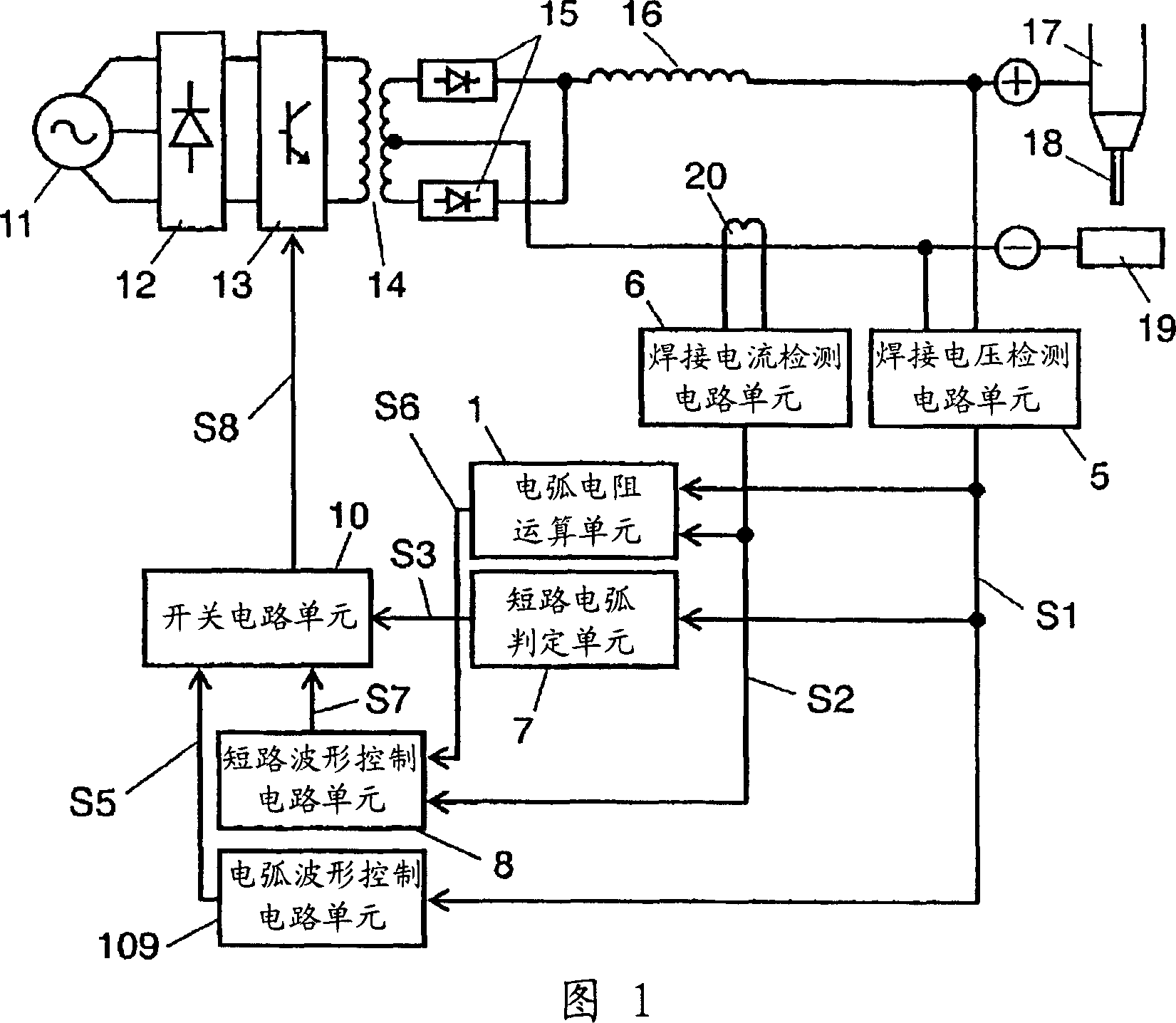
[0049] A consumable electrode type arc welding machine in Embodiment 1 will be described with reference to FIGS. 1 and 2 . The same reference numerals are assigned to the same constituent elements as those of the conventional consumable electrode type arc welding machine described in the background art, and detailed description thereof will be omitted. Furthermore, the main difference between the consumable electrode type arc welding machine of the first embodiment and the conventional one is that the short-circuit waveform control circuit unit 8 is different, and the arc resistance calculation unit 1 described later is newly installed.

[0050]In FIG. 1, the welding voltage detection circuit unit 5 detects a welding voltage and outputs a welding voltage detection signal S1. The welding current detection circuit unit 6 detects a welding current and outputs a welding current detection signal S2. The arc resistance calculation unit 1 receives a welding voltage detection signal ...

Embodiment approach 2

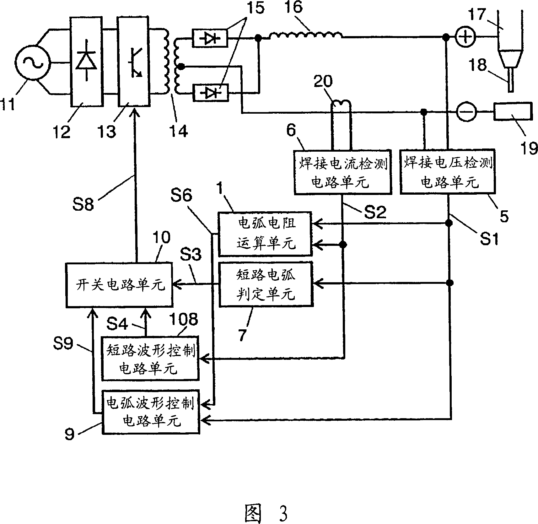
[0054] 3 is a block diagram showing a schematic configuration of a consumable electrode type arc welding machine according to Embodiment 2 of the present invention. In FIG. 3 , the same components as those in Embodiment 1 are assigned the same reference numerals, and detailed description thereof will be omitted. The difference from Embodiment 1 is that the short-circuit waveform control circuit unit 108 is different from the arc waveform control circuit unit 9, and the output of the arc resistance calculation unit 1 is not input to the short-circuit waveform control circuit unit 108 but to the arc waveform control circuit Unit 9 on this.

[0055] In FIG. 3 , arc resistance calculation unit 1 receives welding voltage detection signal S1 from welding voltage detection circuit unit 5 and welding current detection signal S2 from welding current detection circuit unit 6 as inputs. Then, the arc resistance calculation unit 1 calculates an arc resistance value based on these input s...

Embodiment approach 3

[0061] In this embodiment, the same reference numerals are assigned to the same configurations as those in Embodiments 1 and 2, and detailed descriptions are omitted. The main difference between Embodiment 1 and Embodiment 2 is that a constant current control circuit unit 2, a constant current control period setting unit 3, and a second switch circuit unit 4, which will be described later, are provided to perform constant current control when the welding current decreases during the arc period. flow control, thereby preventing arc interruption.

[0062] In Fig. 4, the arc resistance calculation unit 1 calculates the arc resistance value according to the welding voltage detection signal S1 and the welding current detection signal S2, and outputs the calculation result as the arc resistance signal S6 to the constant current control period setting unit 3 and the short circuit waveform control unit 3. The circuit unit 8 and the arc waveform control circuit unit 9 . In the short-c...


PUM


Abstract

In a consumable electrode type arc welding machine, an arc resistance calculator for calculating an arc resistance from the welding current and the welding voltage is provided. The welding current and the welding voltage are controlled by making use of a short-circuit waveform control signal and an arc waveform control signal which change in accordance with the arc resistance signal. This suppresses the sputtering phenomenon and ensures the stability of arc. Furthermore, if arc resistance signal goes higher than a certain specific level for a certain time in an arc period, a constant-current control signal is output so as to control the welding current to be a constant-current with a certain current value that is higher than that output at the moment when arc waveform control signal is output. This prevents the occurrence of an arc break.

Description

technical field [0001] The present invention relates to a consumable-electrode arc welding machine for welding by generating an arc between a welding wire (hereinafter referred to as welding wire) and a welding base material (hereinafter referred to as base material). Background technique [0002] In a conventional consumable-electrode arc welding machine that welds by generating an arc between a welding wire and a base metal, it is generally known to perform voltage control during an arc period and current control during a short-circuit period. These techniques are described, for example, in JP-A-10-109163. [0003] FIG. 5 shows a schematic configuration of a conventional consumable electrode type arc welding machine. In the consumable electrode type arc welding machine shown in FIG. 5 , the output of the three-phase AC input 11 is temporarily rectified into a DC by a diode rectifier circuit 12 . Thereafter, the direct current is converted into a high frequency of tens of...

Claims


Application Information

Patent Timeline
Patent Type & Authority Applications(China)
IPC IPC(8): B23K9/073H02M9/00
CPCB23K9/0734B23K9/092H02M2001/0009H02M3/33507H02M1/0009
Inventor 永野元泰岛林信介
Owner PANASONIC CORP
Why Eureka
Try Eureka