

Device for drying material
A drying and drying part technology, used in drying solid materials, drying gas arrangement, sludge drying, etc.
- Summary
- Abstract
- Description
- Claims
- Application Information
AI Technical Summary
Problems solved by technology
Method used
Image

Examples
Embodiment Construction
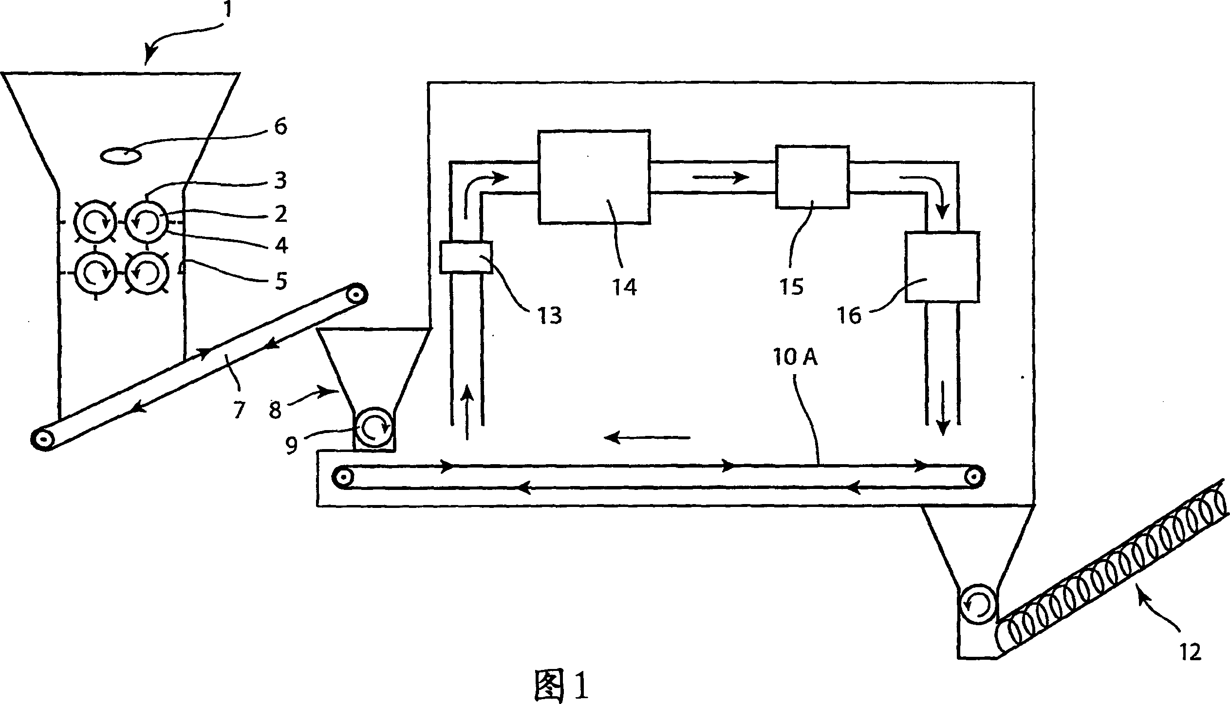
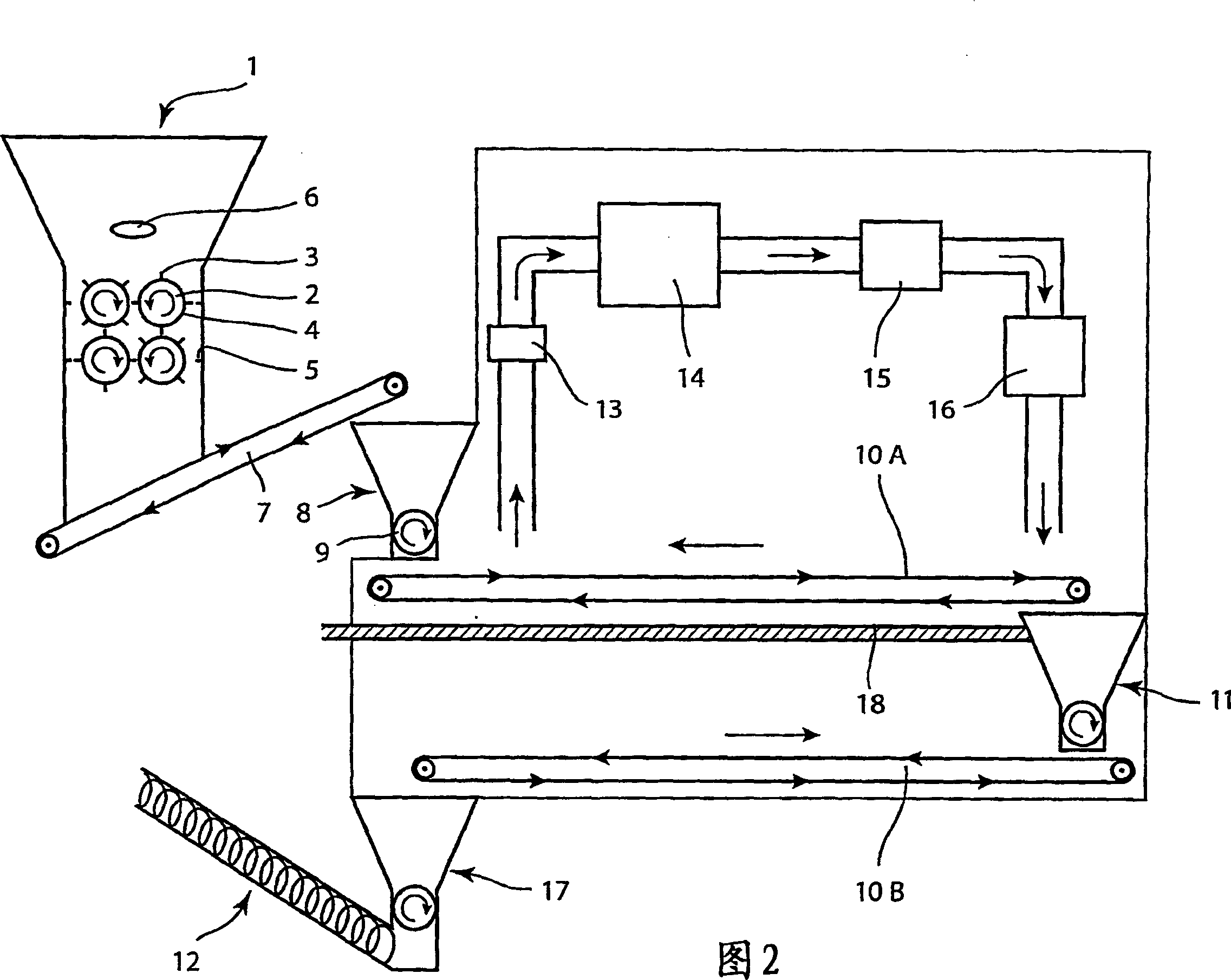
[0025] FIG. 1 shows a grinding machine 1 with two rows of rollers, each row being two rollers 2 . All rolls 2 are equipped with tearing elements 3 . The tearing elements 3 are formed as rods, which have the same thickness along their entire length and are fixed perpendicularly to the outer surface 4 of the roller 2 . The rollers 2 are mounted in such a way that the tearing element 3 almost reaches the outer surface 4 of the adjacent roller. The inside of the walls of the mill 1 is also provided with tearing elements 5 at the level of the first and second row of rollers, so that the tearing elements 3 of the rollers also interfere with these tearing elements 5 .
[0026] Above the first row of rollers 2 there is installed a vibrating device, hereinafter referred to as a vibrator 6 . The purpose of this is to prevent the material added to the grinder 1 from becoming lumpy and thus from falling onto the roller 2 but hanging over it as a bridge. The vibrator 6 vibrates intermit...
PUM
 Abstract
Description
Claims
Application Information