Touch sensitive display

A touch display and display technology, applied in static indicators, instruments, optics, etc., can solve the problems of low thickness and visual function, touch display can not meet the spatial resolution, etc., to achieve high resolution and stability Resolution and clarity, effects to improve visual properties

Inactive Publication Date: 2007-04-04
KONINKLIJKE PHILIPS ELECTRONICS NV
View PDF1 Cites 5 Cited by
  • Summary
  • Abstract
  • Description
  • Claims
  • Application Information

AI Technical Summary

Problems solved by technology

[0005] The problem is that state-of-the-art touch-sensitive displays fail to meet the requirements for spatial resolution, low thickness, and visual functionality

Method used


Image

  • Touch sensitive display
  • Touch sensitive display
  • Touch sensitive display

Examples


Embodiment Construction

[0039] The pursuit of high-performance, high-speed video, large-size, and low-power displays has pushed display technology toward active-matrix (AM) liquid crystal display (LCD) technology. Various active matrix liquid crystal display devices are suitable for the present invention. The following specific examples illustrate the present invention relating to active matrix liquid crystal display devices by way of example only. It should be understood that other types of active matrix liquid crystal display devices may also be used, for example, devices using electrophoretic inks, poly LEDs, OLEDs, plasma displays and flexible variations thereof.

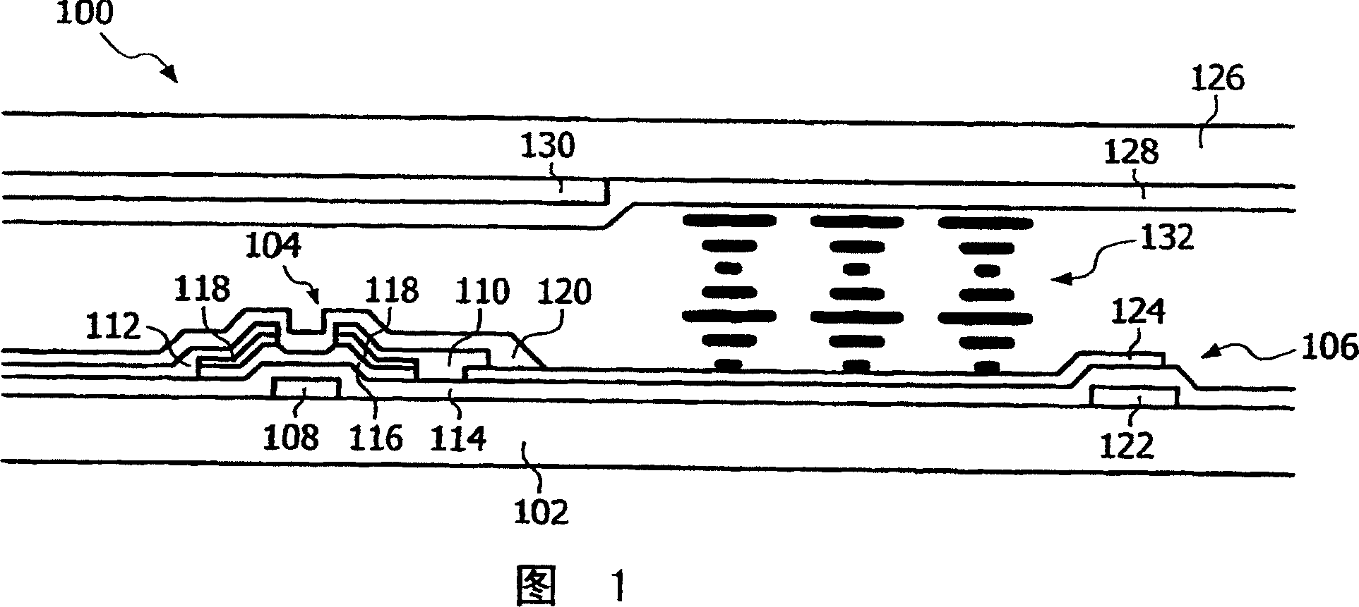
[0040] To illustrate the integration of haptic features in AMLCD technology, reference is made to FIG. 1 , which is a schematic cross-sectional view showing a typical AMLCD 100 . Liquid crystal 132 is interposed between passive substrate 126 and active substrate 102 . Furthermore, each pixel has a driving TFT 104 and a storage capaci...


PUM


Abstract

There is provided a touch sensitive display comprising a passive substrate, an active substrate, and a display material disposed between the passive and active substrates, wherein driving circuitry for driving a pixel of the display and touch sensing circuitry are arranged on the active substrate. The touch sensing circuitry comprises at least one component with a first and a second electrode, wherein the electrodes are arranged to displace with respect to each other in response to a touch input.

Description

technical field [0001] The present invention relates to a touch display. Background technique [0002] The market for hand-held and portable consumer electronics and computing products has diversified significantly over the past decade. This trend toward smaller devices that can display increasing amounts of information has led to improved displays with higher resolutions. [0003] Also, user interfaces have evolved rapidly, and much research has been devoted to coming up with intuitive interactive mechanisms. A common method of receiving user input is to have a touch-sensitive display on the device. This enables user interaction by the user touching the touch-sensitive display. [0004] WO 03 / 079449A1 discloses an AM electroluminescent display device comprising a pressure sensor structure comprising a transparent upper electrode layer, a lower conductive barrier layer and a compressible layer of insulating or highly resistive material superimposed on a transparent upper ...

Claims


Application Information

Patent Timeline
Patent Type & Authority Applications(China)
IPC IPC(8): G06F3/033G02F1/133G06F3/041G06F3/044
CPCG06F3/0412G02F1/13394G06F3/044G06F3/0445G02F1/133
Inventor M·H·W·M·范德尔登J·T·M·范比克G·J·A·德斯图拉A·L·A·M·肯默伦
Owner KONINKLIJKE PHILIPS ELECTRONICS NV
Why Eureka
Try Eureka