Electromagnetic impact device for controlling welding heat cracking and deformation

A thermal cracking and electromagnetic technology, applied in the direction of welding equipment, auxiliary equipment, welding equipment, etc., can solve the problems such as the difficulty of quantifying the size of the impact force, the inability to reduce the lateral shrinkage of the weld seam, and the large vibration of the hammerhead deflection. Simple, easy mechanical force transmission, low cost effect

Inactive Publication Date: 2007-04-11
HARBIN INST OF TECH
View PDF1 Cites 13 Cited by
  • Summary
  • Abstract
  • Description
  • Claims
  • Application Information

AI Technical Summary

Problems solved by technology

[0003] The purpose of the present invention is to solve the problem that the existing static and dynamic stretching devices cannot reduce the lateral shrinkage of the weld seam, the production efficiency is low, and the operation is complicated; the equipment of the welding rolling device is huge, and the rolling wheel is easy to interfere with the welding torch, resulting in arcing; The hammer head deflection vibration of the welding hammer device is relatively large, and a guiding mechanism needs to be added; the impact force of the welding impact rolling device is difficult to quantify, and it is not suitable for welding of medium-thick structures and materials with high hardness. A device for controlling welding thermal cracks and deformation with welding electromagnetic shock

Method used


Image

  • Electromagnetic impact device for controlling welding heat cracking and deformation
  • Electromagnetic impact device for controlling welding heat cracking and deformation
  • Electromagnetic impact device for controlling welding heat cracking and deformation

Examples


specific Embodiment approach 1

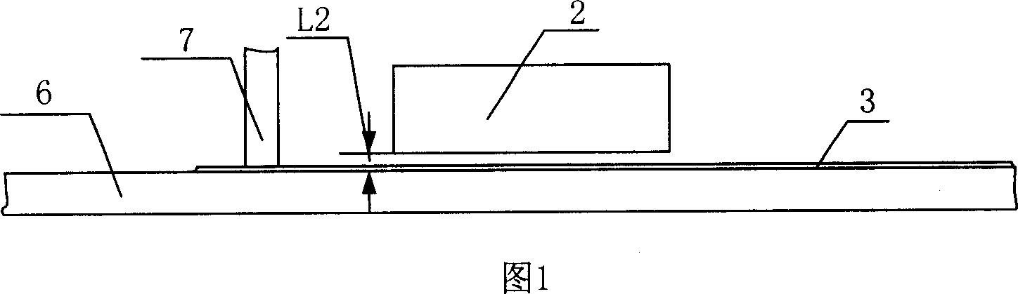
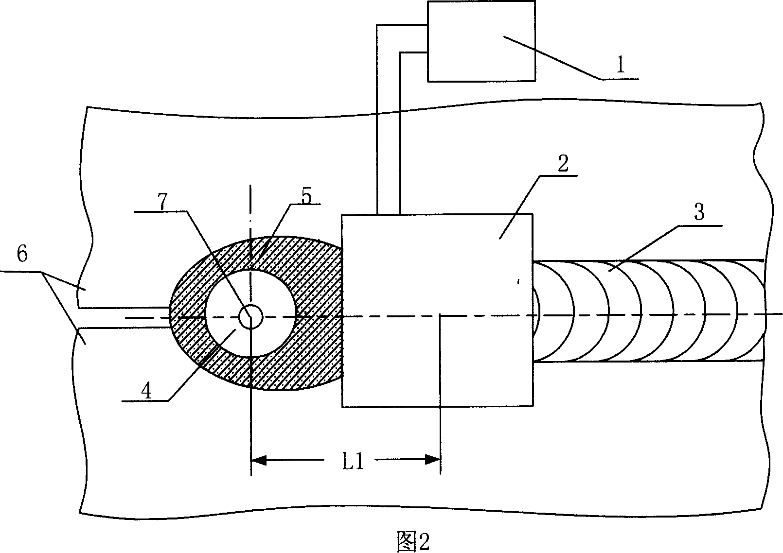
[0007] Specific embodiment one: this embodiment is described in conjunction with Fig. 1, Fig. 2, Fig. 3, Fig. 4, and this embodiment is made up of pulse discharge circuit 1, coil 2; The coil 2 is set directly above the welding seam 3, the distance L2 between the lower surface of the coil 2 and the upper surface of the welding seam 3 is 2-5mm, and the distance L1 between the center of the coil 2 and the center of the welding torch 7 It is 25-60mm.

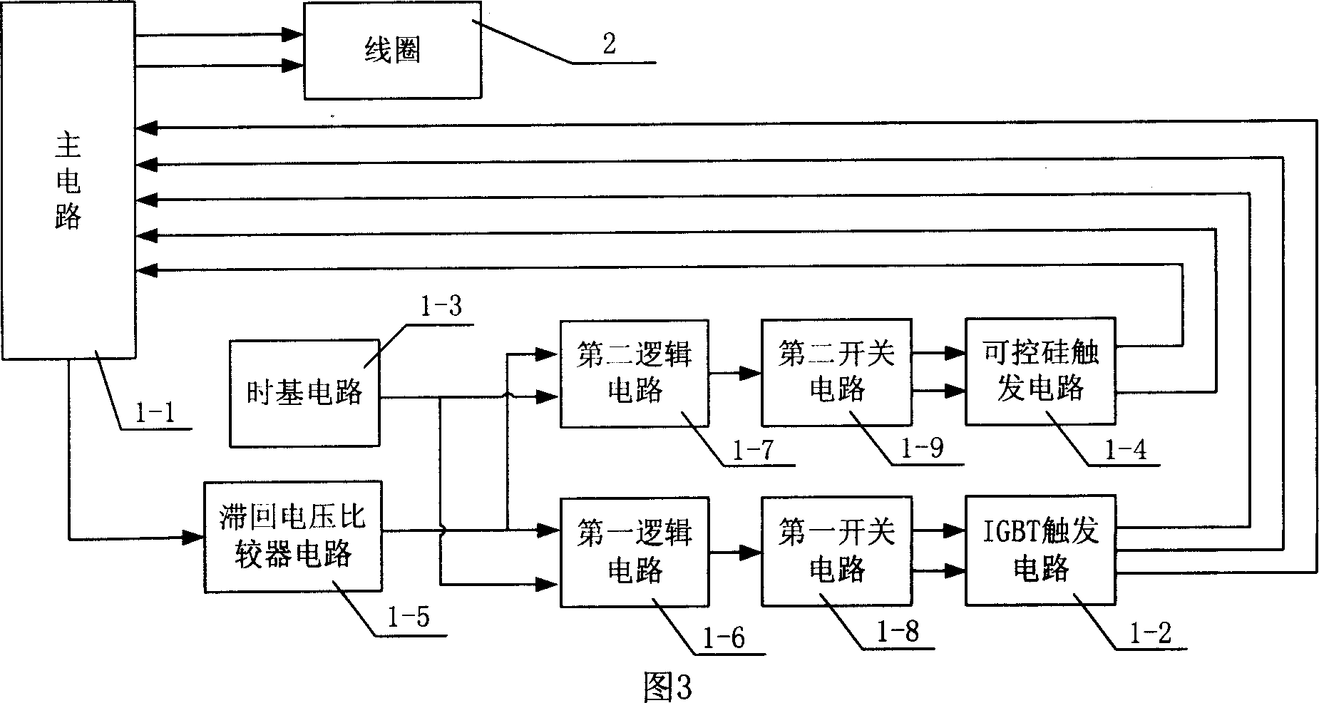
[0008] Pulse discharge circuit 1 is composed of main circuit 1-1, IGBT trigger circuit 1-2, time base circuit 1-3, thyristor trigger circuit 1-4, hysteresis voltage comparator circuit 1-5, first logic circuit 1- 6. The second logic circuit 1-7, the first switch circuit 1-8 and the second switch circuit 1-9 are composed;

[0009]The voltage signal output end of the main circuit 1-1 is connected to the input end of the hysteresis voltage comparator circuit 1-5, and the output end of the hysteresis voltage comparator circuit 1-5 is co...

specific Embodiment approach 2

[0011] Specific Embodiment 2: This embodiment is described in conjunction with Fig. 1 and Fig. 2. The difference between this embodiment and Embodiment 1 is that the distance L1 from the center of the coil 2 to the center of the welding torch 7 is 25-45 mm, and other components and structures are the same as those of Embodiment 1. same.

specific Embodiment approach 3

[0012] Specific embodiment three: This embodiment is described in conjunction with Fig. 1 and Fig. 2. The difference between this embodiment and embodiment two is that the distance L1 from the center of the coil 2 to the center of the welding torch 7 is 26 mm, and other components and structures are the same as in the second embodiment.


PUM


Abstract

The present invention relates to welding technology, and is one kind of electromagnetic impact device for controlling welding heat crack and deformation. The electromagnetic impact device includes one pulse discharge circuit, and one coil with two input ends connected to the output of the pulse discharge circuit. The coil is set over the weld seam, and has lower surface apart from the upper surface of the weld seam by 2-5 mm and center in the distance to the center of the welding torch of 25-60 mm. The present invention has simple operation, easy control on energy, small size, low cost, stereo electromagnetic impact force and no need of contacting the coil with the welded workpiece.

Description

technical field [0001] The invention relates to the technical field of controlling welding hot crack and deformation. Background technique [0002] Welding hot cracks, welding residual stress and residual deformation are common problems in the welding process. In order to solve the above problems, various devices for controlling residual stress and residual deformation have been proposed at home and abroad, such as static and dynamic temperature difference stretching, rolling with welding Pressure, hammering with welding and impact rolling device with welding etc., but the above-mentioned devices all have their weak points. Static and dynamic stretching devices cannot reduce the lateral shrinkage of the weld, and the production efficiency is low and the operation is complicated. The welding rolling device is huge, and the rolling wheel is easy to interfere with the welding torch, resulting in arcing. The welding hammering device has the disadvantages that the hammer head d...

Claims


Application Information

Patent Timeline
Patent Type & Authority Applications(China)
IPC IPC(8): B23K37/00B23K9/32B23K9/10
Inventor 方洪渊徐文利杨建国刘雪松许威
Owner HARBIN INST OF TECH
Why Eureka
Try Eureka