
Active hydraulic energy storage device loop

A technology of hydraulic accumulator and hydraulic pipeline, applied in the direction of accumulator device, fluid pressure actuating device, etc., can solve problems such as inconvenience of use, improve acceleration and deceleration ability, improve adaptability and power utilization rate Effect

Inactive Publication Date: 2007-04-11
TAIYUAN UNIV OF TECH
View PDF0 Cites 11 Cited by
  • Summary
  • Abstract
  • Description
  • Claims
  • Application Information

AI Technical Summary

Problems solved by technology

However, at present, the accumulator is generally installed directly at the outlet of the hydraulic pump during use. Only when the pressure of the system is higher than the internal pressure of the accumulator can the external energy be stored in the accumulator, and only When the pressure in the accumulator is higher than the pressure of the hydraulic system, energy can be supplied to the outside, and the process of storing and supplying energy is affected by the pressure difference between the inside and outside, which is generally uncontrollable
In order to overcome this deficiency, although some people in foreign countries have proposed to control the process of storing and discharging energy in the accumulator by changing the pressure of the pre-charged gas in the accumulator, each system needs to add a set of complicated charging and exhausting devices. It is very inconvenient, so in order to be able to not be affected by the internal and external pressure of the accumulator during the process of controlling the energy flow of the accumulator, the present invention proposes an active hydraulic accumulator control circuit with active functions

Method used

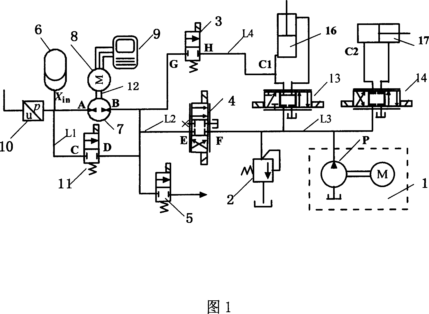
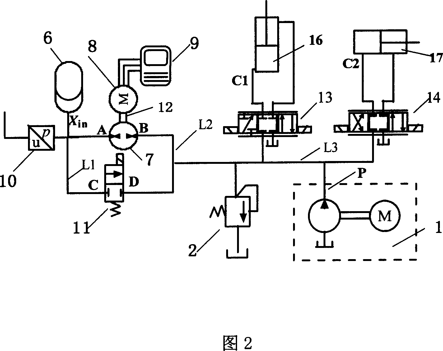
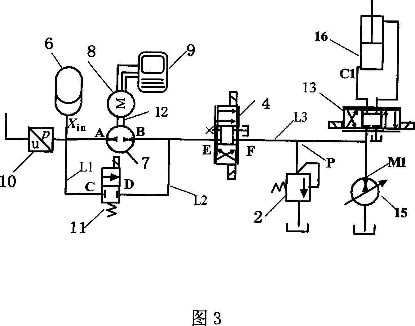

Image

  • Active hydraulic energy storage device loop
  • Active hydraulic energy storage device loop
  • Active hydraulic energy storage device loop

Examples


Embodiment approach 1

[0013] The active hydraulic accumulator circuit of the present invention is composed of a hydraulic power source 1, a safety valve 2, a two-position two-way electric control valve I 3, a directional control valve 4, a two-position two-way electric control valve II 5, and a hydraulic accumulator 6 , hydraulic pump 7, electric motor 8, motor speed controller 9, pressure sensor 10, two-position two-way electric control valve III 11, coupling 12, hydraulic cylinder I 16, hydraulic cylinder II 17, hydraulic pipelines L1, L2, L3, L4 and ports A, B, C, D, E, F, G, H, P, x in , The hydraulic cylinder is composed of rodless cavity C1, C2 and so on. The hydraulic power source 1 is a device that provides power to the entire system, and it can be in any form that can be used at present. Safety valve 2 is to limit the maximum pressure of the system and play a role in safety protection of the system. Two-position two-way electric control valve I 3, directional control valve 4, two-positio...

Embodiment approach 2

[0017] The active hydraulic accumulator circuit of the present invention is as described in Embodiment 1, and the hydraulic pipeline L2 can be directly communicated with the hydraulic pipeline L3 without passing through the directional control valve 4 .

Embodiment approach 3

[0019] The active hydraulic accumulator circuit of the present invention is described in Embodiment 1, and more than one accumulator 6 is provided to form an accumulator group; more than one two-position two-way electric control valve II 5 is set on the pipeline L2 to communicate with one The above hydraulic cylinder II 17 constitutes multiple sets of two-position two-way electronically controlled valves and hydraulic cylinders, thereby constituting a multi-unit active hydraulic accumulator circuit.


PUM


Abstract

The active hydraulic energy accumulating device loop has increased hydraulic pump, motor, motor rotation speed controller and direction controlling valve in the hydraulic power source. The oil port of the hydraulic pump and the oil port of the electrically controlling valve are communicated via hydraulic pipes to the oil port of the hydraulic energy accumulating device and connected via hydraulic pipes to hydraulic pipe communicated to the power source; the motor drives the hydraulic pump to rotate; the motor rotation speed controller controls the rotation speed and direction of the motor and the pressure inside the hydraulic energy accumulating device with the system signal; and the pressure sensor is connected to the inlet of the hydraulic energy accumulating device. The active hydraulic energy accumulating device loop has raised adaptability and power utilizing rate and raised speed varying capacity.

Description

technical field [0001] The invention belongs to the technical field of hydraulic accumulator control, in particular to a control circuit that uses an active hydraulic accumulator to actively store or supplement energy. Background technique [0002] Accumulator is a widely used component in hydraulic technology. Its main function is to absorb and store excess flow in the system. When the flow of the system pump source is insufficient, the energy stored in it will be supplied to the system. Hydraulic systems using accumulators can reduce installed power and have high energy utilization. However, at present, the accumulator is generally installed directly at the outlet of the hydraulic pump during use. Only when the pressure of the system is higher than the pressure inside the accumulator can the external energy be stored in the accumulator. When the pressure in the accumulator is higher than the pressure of the hydraulic system, energy can be supplied to the outside, and the ...

Claims


Application Information

Patent Timeline
Patent Type & Authority Applications(China)
IPC IPC(8): F15B1/033F15B15/18
Inventor 权龙李敏秦太龙
Owner TAIYUAN UNIV OF TECH
Learn More