Rotating fluid machine
A fluid machinery, rotary technology, used in rotary piston machinery, rotary piston engines, rotary piston pumps, etc., can solve the problems of reduced compression efficiency, refrigerant leakage, gas leakage, etc., to reduce the useless volume. Effect
- Summary
- Abstract
- Description
- Claims
- Application Information
AI Technical Summary
Problems solved by technology
Method used
Image

Examples
Embodiment approach 1
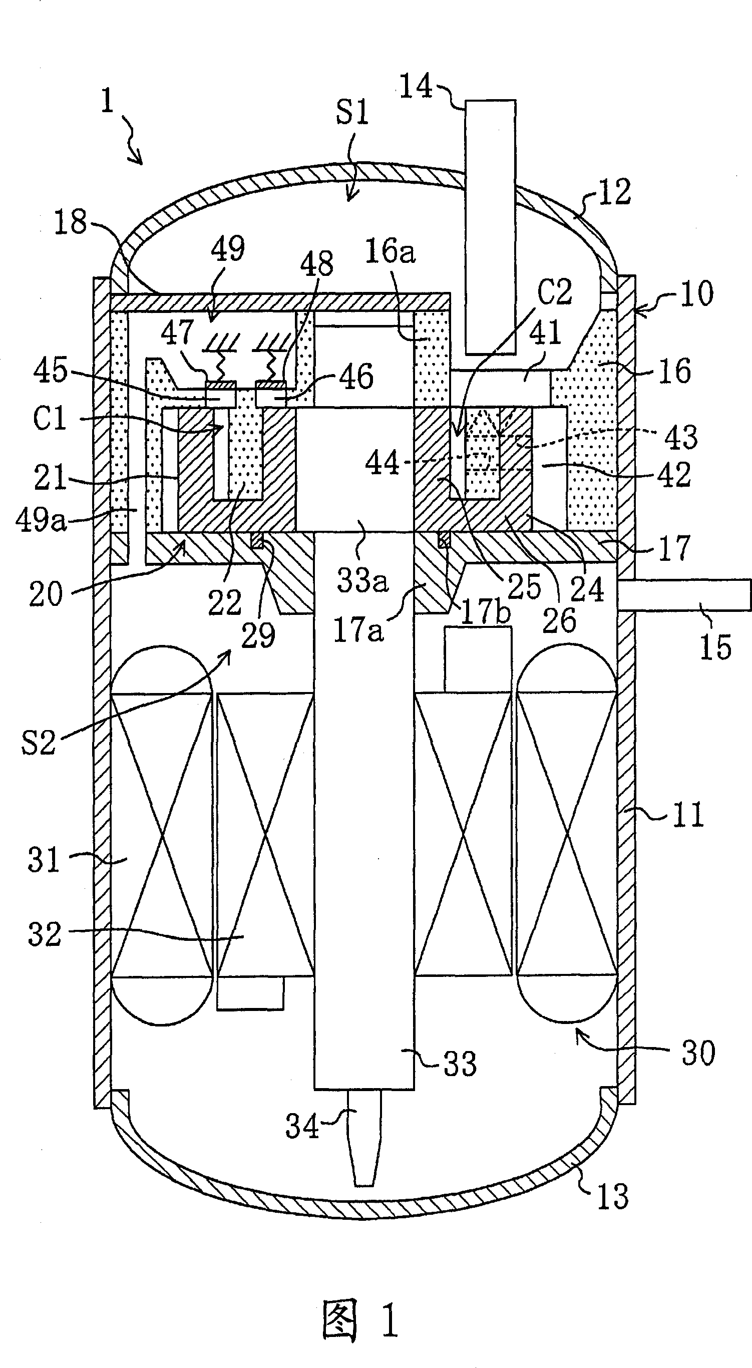
[0096] This embodiment relates to a rotary compressor. As shown in FIG. 1 , the compressor 1 is configured as a hermetically sealed type, and a compression mechanism (eccentrically rotating piston mechanism) 20 and a motor (drive mechanism) 30 are accommodated in a housing 10 of the compressor 1 . The above-mentioned compressor 1 is used, for example, to compress a refrigerant sucked in from an evaporator in a refrigerant circuit of an air-conditioning apparatus, and then discharge the refrigerant to a condenser.
[0097] The housing 10 is composed of a cylindrical body 11 , an upper end plate 12 fixed to the upper end of the body 11 , and a lower end plate 13 fixed to the lower end of the body 11 . The upper end plate 12 is provided with a suction pipe 14 penetrating the end plate 12 , and the trunk portion 11 is provided with a discharge pipe 15 penetrating the trunk portion 11 .
[0098] The compression mechanism 20 is configured between the upper casing 16 and the lower c...
Embodiment approach 2
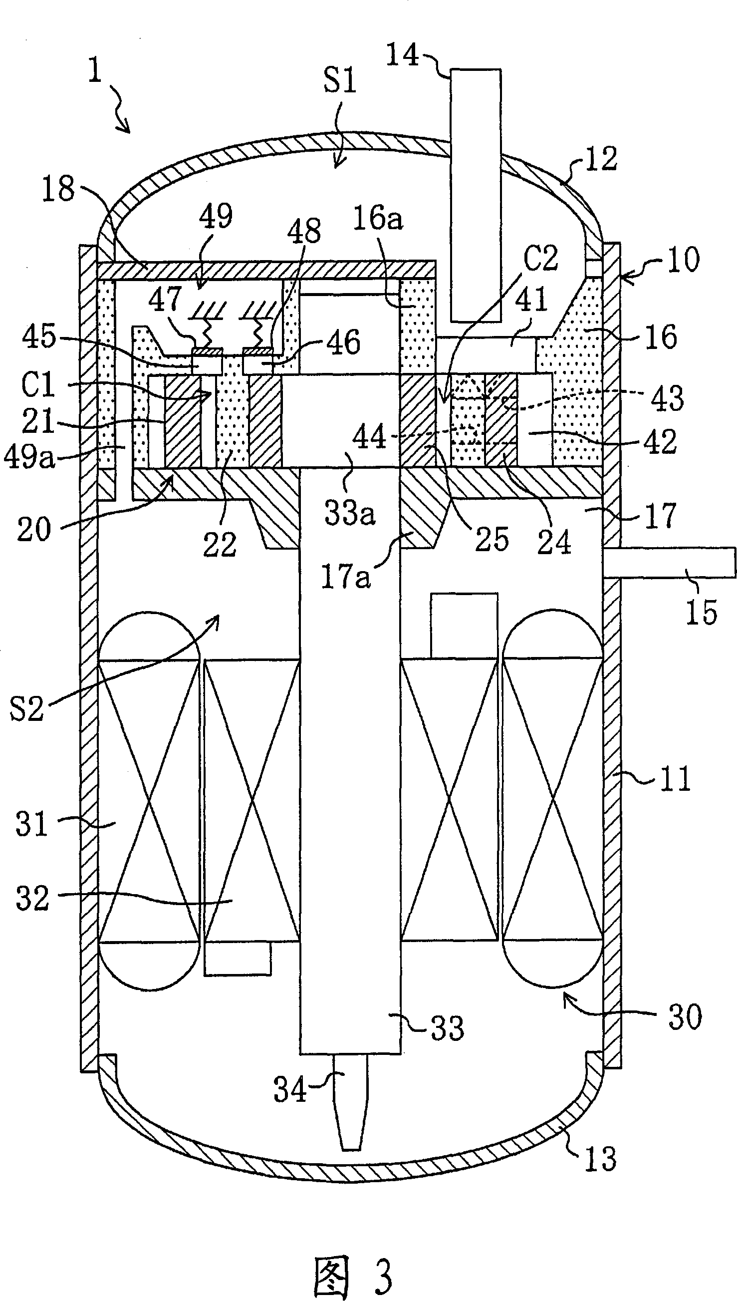
[0150] The second embodiment of the present invention is an example in which the arrangement of the compression mechanism 20 and the electric motor 30 in the housing 10 is different from that of the first embodiment.
[0151] As shown in FIG. 8 , in the second embodiment, the compression mechanism 20 is arranged in the lower part of the housing 10 , and the motor 30 is arranged in the upper part. The compression mechanism 20 is formed between the upper casing 16 and the lower casing 17 fixed to the lower portion of the housing 10 , and the annular piston 22 is integrally formed with the upper casing 16 . Outer cylinder 24 , inner cylinder 25 , and end plate 26 are integrally formed. Inner cylinder 25 is slidably fitted on eccentric portion 33 a of drive shaft 33 to hold cylinder 21 between upper housing 16 and lower housing 17 . In addition, bearing portions 16 a and 17 a for supporting the drive shaft 33 are formed on the upper housing 16 and the lower housing 17 , respective...
Embodiment approach 3
[0161] The third embodiment of the present invention is an example in which the local structure of the compression mechanism 20 is different from that of the first embodiment.
[0162] In this third embodiment, as shown in FIG. 9 , the vertical relationship of the compression mechanism 20 itself is reversed from that of the first embodiment, and the suction structure is changed. Specifically, the cylinder 21 is integrally formed by connecting the upper ends of the outer cylinder 24 and the inner cylinder 25 with the end plate 26 . In addition, the annular piston 22 is integrally formed with the lower housing 17 . The seal ring 29 is filled in an annular groove 16 b formed in the upper housing 16 , and is crimped on the upper surface of the end plate 26 of the cylinder 21 .
[0163] The suction pipe 14 is provided laterally on the trunk portion 11 of the housing 10 , and a suction port 41 communicating with the suction pipe 14 is formed in the lower casing 17 . In addition, f...
PUM
 Abstract
Description
Claims
Application Information
 - R&D
- Intellectual Property
- Life Sciences
- Materials
- Tech Scout
- Unparalleled Data Quality
- Higher Quality Content
- 60% Fewer Hallucinations
Browse by: Latest US Patents, China's latest patents, Technical Efficacy Thesaurus, Application Domain, Technology Topic, Popular Technical Reports.
© 2025 PatSnap. All rights reserved.Legal|Privacy policy|Modern Slavery Act Transparency Statement|Sitemap|About US| Contact US: help@patsnap.com