

Method of manufacturing the anti-wear sintered member, sintered valve seat, and method of manufacturing the same
A manufacturing method and technology of sintering valve seats, which are applied in the field of manufacturing wear-resistant sintered parts, can solve the problem of engine life that cannot be said to be solved.
- Summary
- Abstract
- Description
- Claims
- Application Information
AI Technical Summary
Problems solved by technology
Method used
Image

Examples
Embodiment 1
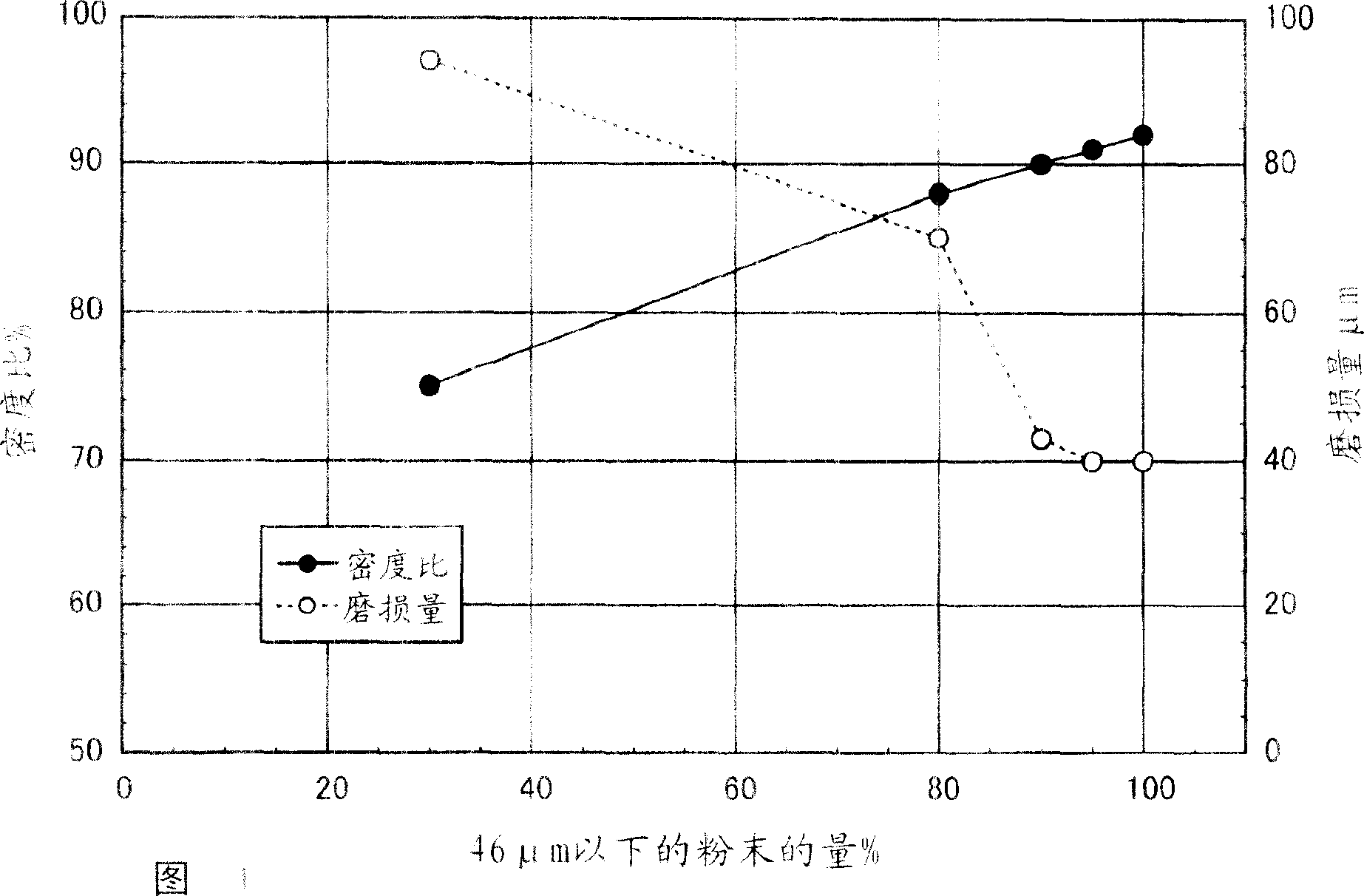
[0108] As the matrix forming powder, prepare a stainless steel powder corresponding to JIS standard SUS316 having the particle size composition shown in Table 1. As the hard phase forming powder, prepare the mass ratio by Mo: 28%, Si: 2.5%, Cr: A Co-based alloy powder composed of 8%, the balance of Co and unavoidable impurities was added and mixed with 60% by mass of a hard phase-forming powder to the matrix-forming powder to obtain a raw material powder. The raw material powder was compacted into a disc shape with a diameter of 30 mm and a thickness of 10 mm under a molding pressure of 1.2 GPa, and the compact obtained in this way was sintered at 1250°C×1Hr in an ammonia atmosphere to produce sample No. 01- 05 samples. These samples were subjected to a reciprocating sliding friction test while measuring the density ratio, and the amount of wear after the test was measured. Table 1 shows these results together.
[0109] The reciprocating sliding friction test is a friction t...
Embodiment 2
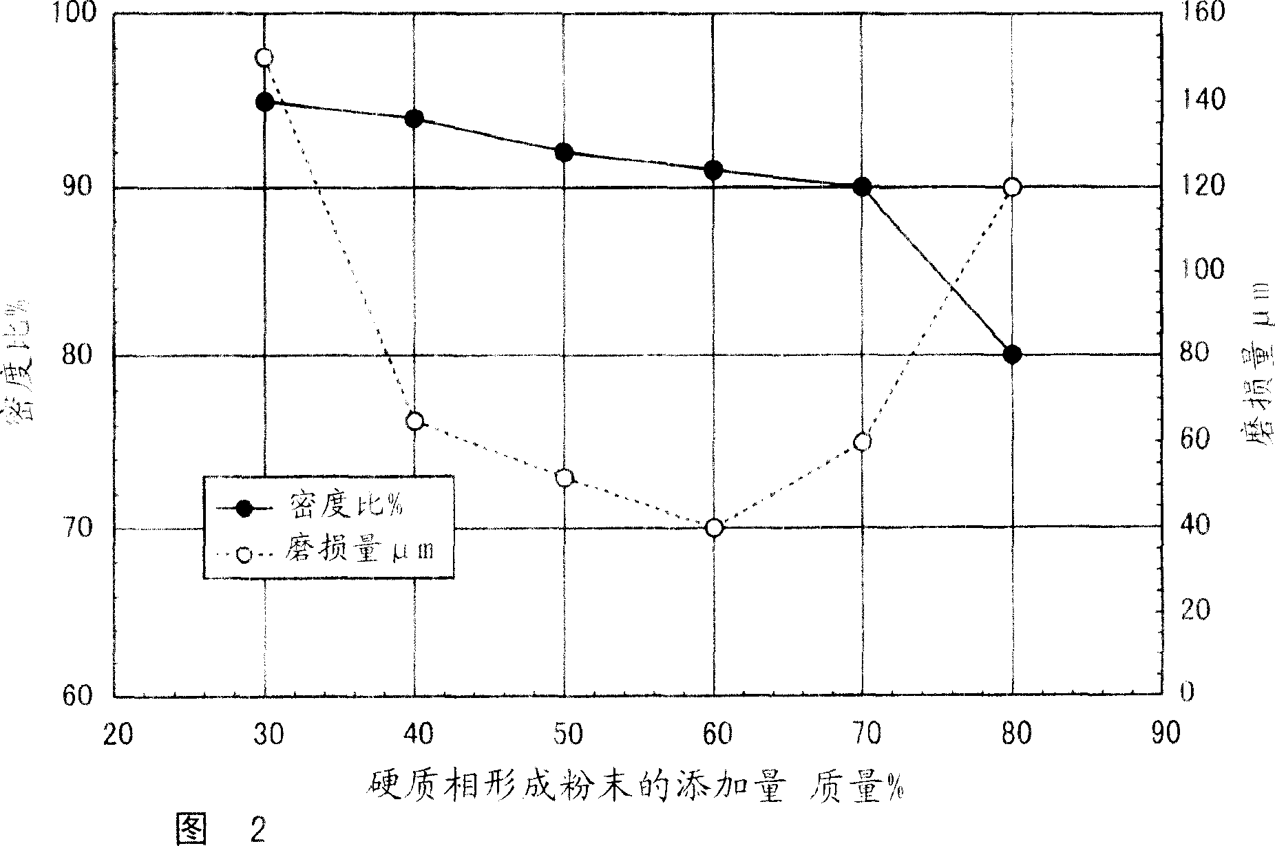
[0113] As a matrix forming powder, a stainless steel powder corresponding to JIS standard SUS316 with a powder ratio of 46 μm or less used in the sample number 02 of Example 1 of 95% was prepared, and as a hard phase forming powder, it was prepared to be used in Example 1. The Co-based alloy powders were mixed in the ratio shown in Table 2 to obtain raw material powders. Using this raw material powder, powder compaction was performed under the same conditions as in Example 1, followed by sintering to produce a sample of sample number 06-10. For these samples, the same test as in Example 1 was performed, and the test results are shown in Table 2 and FIG. 2 together with the test results of sample number 02 in Example 1.
[0114]
[0115] As can be seen from FIG. 2 , sample No. 06 in which the amount of hard phase-forming powder added was less than 40% by mass had a high density ratio, but the dispersion amount of hard phase was small, resulting in a large amount of we...
Embodiment 3
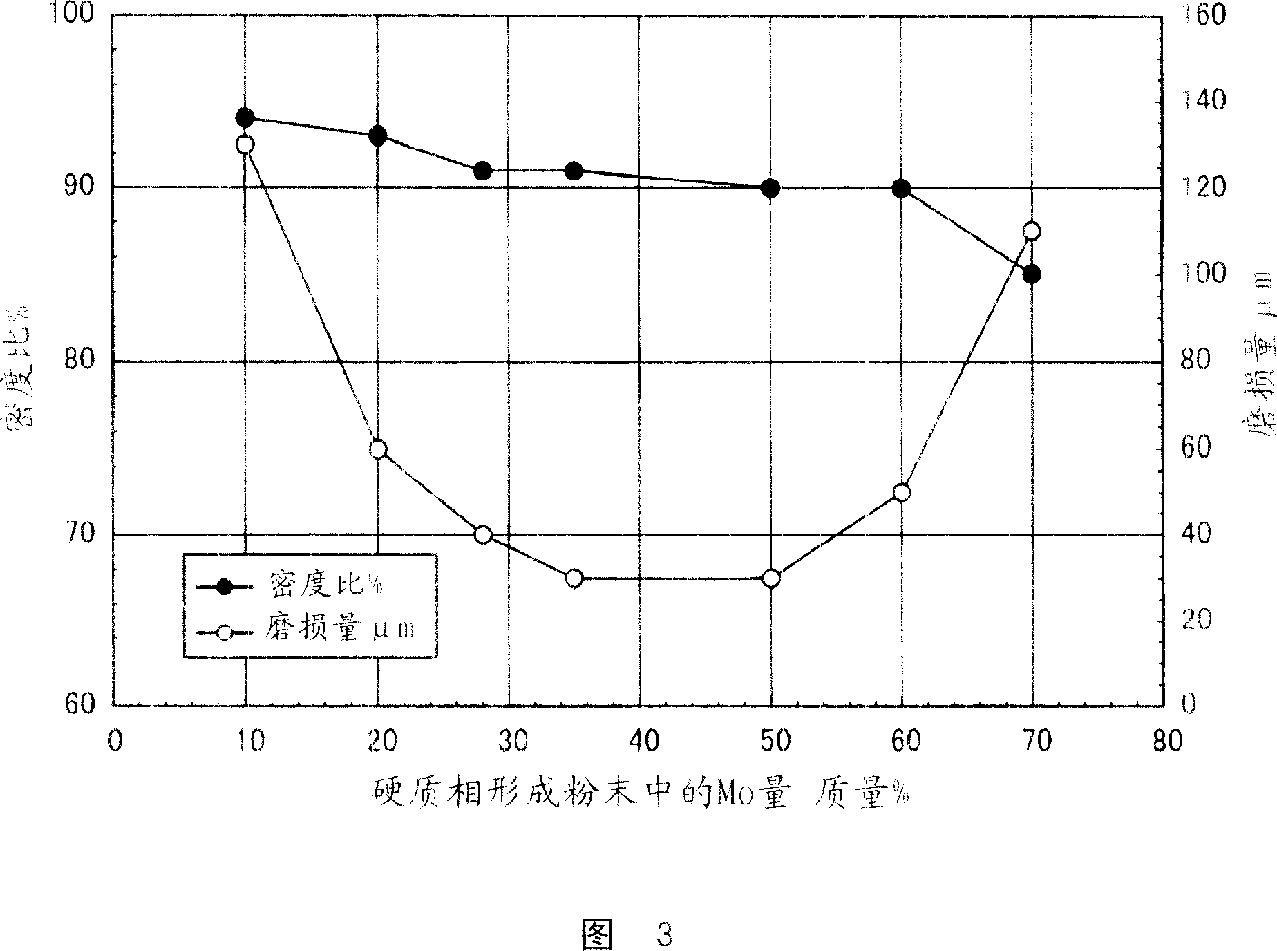
[0117] As the matrix forming powder, a stainless steel powder corresponding to JIS standard SUS316 in which the proportion of the powder of 46 μm or less used in the sample number 02 of Example 1 was 95% was prepared, and as the hard phase forming powder, the composition shown in Table 3 was prepared. The Co-based alloy powder was added and mixed with 60% by mass of the hard phase-forming powder to the matrix-forming powder to obtain a raw material powder. Using these raw material powders, powder compaction was carried out under the same conditions as in Example 1, followed by sintering to prepare samples of sample numbers 11-16. These samples were subjected to the same test as in Example 1, and the test results are shown in Table 3 and FIG. 3 together with the evaluation results of sample No. 02 in Example 1.
[0118] sample
[0119] It is clear from FIG. 3 that sample No. 11, in which the amount of M0 in the Co-based alloy powder used as a hard phase is less than 2...
PUM
| Property | Measurement | Unit |
|---|---|---|
| particle diameter | aaaaa | aaaaa |
Abstract
Description
Claims
Application Information