Smoke inlet device of incinerator

A technology for incinerators and flue gas, applied in the field of flue gas import devices, to achieve the effects of prolonging residence time, low cost, and increasing the number of cycles of convective exchanges

Inactive Publication Date: 2011-09-21
GUIYANG AL-MG DESIGN & RES INST
View PDF0 Cites 0 Cited by
  • Summary
  • Abstract
  • Description
  • Claims
  • Application Information

AI Technical Summary

Problems solved by technology

[0003] The object of the present invention is to provide a flue gas inlet device for an incinerator that can prolong the residence time of the flue gas in the furnace, so that the flue gas can be completely burned, thereby improving environmental pollution, so as to solve the problems existing in the prior art

Method used


Image

  • Smoke inlet device of incinerator
  • Smoke inlet device of incinerator
  • Smoke inlet device of incinerator

Examples


Embodiment Construction

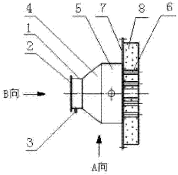
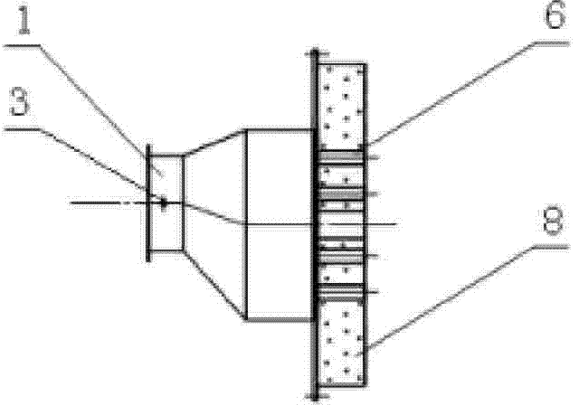
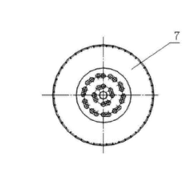
[0012] Embodiments of the present invention: as figure 1 As shown, it consists of flue gas inlet pipe 1, flue gas inlet connecting flange 2, flue gas inlet monitoring pipe 3, flue gas special-shaped pipe 4, flue gas pipe 5, flue gas inlet piping 6, and piping flange 7. The gas inlet connection flange 2 is welded on the port of the flue gas inlet pipe 1, the flue gas inlet monitoring pipe 3 is welded on the side wall of the flue gas inlet pipe 1, the flue gas inlet pipe 1 and the flue gas special-shaped pipe 4, the flue gas pipe 5. The piping flanges 7 are welded together in turn. The flue gas inlet piping 6 is divided into inner and outer circles at the center point, and welded (or bolted) on the piping flange 7 in a double ring shape, and then refractory castables are used. 8. Pouring the flue gas inlet pipe 6 and the pipe flange 7 into one. In order to make the incoming flue gas form a circular vortex shape, one end of the flue gas inlet pipe 6 is welded to the pipe flange ...


PUM


Abstract

There is disclosed a flue gas inlet device of an incinerator, which consists of a the gas inlet pipe, a flue gas inlet connecting flange, a fuel gas inlet monitoring pipe, a flue gas special pipe, a flue gas pipe, a flue gas inlet fitting pipe and a fitting pipe flange. The flue gas inlet connecting flange and the flue gas inlet monitoring pipe are connected on the flue gas inlet pipe connected with the flue gas special pipe. The flue gas special pipe is connected with the flue gas pipe connected with the fitting pipe flange. The flue gas inlet fitting pipe is connected on the fitting pipe flange and using the refractory pouring material is used for pouring the flue gas inlet fitting pipe and the fitting flange to be an integral one.

Description

Technical field: [0001] The invention relates to a flue gas inlet device of an incinerator. Background technique: [0002] At present, the domestic asphalt flue gas collected from the blast furnace (kneading, molding) enters the incinerator and the flue gas from the tail of the rotary kiln enters the ash chamber. The short residence time and incomplete combustion of the flue gas cause certain pollution to the environment, which has become a difficult problem that has been wanted to be solved for a long time but has not been solved. Invention content: [0003] The object of the present invention is to provide a flue gas inlet device for an incinerator that can prolong the residence time of the flue gas in the furnace so that the flue gas can be completely burned, thereby improving environmental pollution, so as to solve the problems in the prior art. [0004] The present invention is constituted as follows: it consists of a flue gas inlet pipe (1), a flue gas inlet connect...

Claims


Application Information

Patent Timeline
Patent Type & Authority Patents(China)
IPC IPC(8): F23G7/06
Inventor 陈书昌杨西
Owner GUIYANG AL-MG DESIGN & RES INST
Why Eureka
Try Eureka