Fuel combustion supporting system capable of improving fuel combustion efficiency

A technology of combustion efficiency and combustion-supporting system, applied in the direction of adding non-fuel substances to fuel, charging system, combustion method, etc., can solve problems such as insufficient combustion, and achieve the effect of protecting the environment and increasing the combustion temperature

Pending Publication Date: 2018-06-08
北京清旺新能源科技有限公司 +1
View PDF5 Cites 0 Cited by
  • Summary
  • Abstract
  • Description
  • Claims
  • Application Information

AI Technical Summary

Problems solved by technology

[0005] The purpose of the present invention is to provide a fuel combustion combustion-supporting system that improves fuel combustion efficiency, and solves the problem that the existing fuel cannot be fully combusted under the state of natural air oxygen supply

Method used


Image

  • Fuel combustion supporting system capable of improving fuel combustion efficiency
  • Fuel combustion supporting system capable of improving fuel combustion efficiency
  • Fuel combustion supporting system capable of improving fuel combustion efficiency

Examples


Embodiment 1

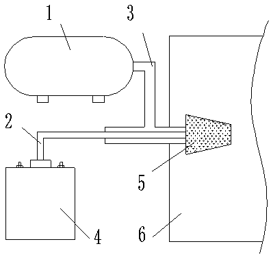
[0039] Example 1: In figure 1 Among them, the combustion system includes: fuel container 1, HHO gas delivery pipe 2, fuel delivery pipe 3, HHO generator 4, combustion-supporting reactor 5 and combustion device 6; the outlet of HHO generator 4 is connected with HHO gas delivery pipe 2, and the fuel The outlet of the container 1 is connected with a fuel delivery pipe 3, and the front ends of the HHO gas delivery pipe 2 and the fuel delivery pipe 3 have a combustion-supporting reactor 5, and the combustion-supporting reactor 5 is placed in a combustion device 6.

[0040] Said fuel includes: natural gas, coal, heavy oil, diesel, gasoline, kerosene, shale gas, biomass fuel, etc.

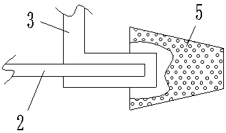
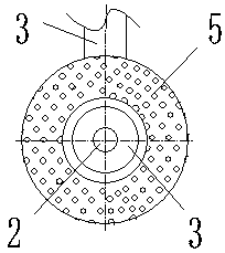
[0041] exist figure 2 , image 3 In the HHO gas delivery pipe 2 and the fuel delivery pipe 3, the HHO gas delivery pipe 2 penetrates into the fuel delivery pipe 3, and at the contact part where the HHO gas delivery pipe 2 and the fuel delivery pipe 3 penetrate, the fuel delivery pipe 3 and the outer w...

Embodiment 2

[0048] Example 2: In Figure 4 , Figure 5 Among them, the HHO gas delivery pipe 2 and the fuel delivery pipe 3 are connected in parallel. Others are the same as in Example 1.

Embodiment 3

[0049] Example 3: In Figure 9 Among them, the burner is a fuel engine 7. Fuel engine 7 includes: air filter 7-1, fuel tank 7-2, engine air supply pipe 7-3, engine exhaust pipe 7-4 and engine fuel supply pipe 7-5; Air intake port, exhaust port and fuel intake port, air filter 7-1 is connected with air intake port by engine air supply pipe 7-3, and the fuel oil in the fuel tank 7-2 passes engine fuel supply pipe 7- 5. It is connected to the fuel inlet, and the engine exhaust pipe 7-4 is discharged through the exhaust pipe of the fuel engine; the engine air supply pipe 7-3 is connected to the HHO gas delivery pipe 2, and the other end of the HHO gas delivery pipe 2 is connected to the HHO The HHO generator gas outlet 4-6 of the generator 4 is connected; the HHO gas generated by the HHO generator and the gas of the air filter 7-1 are delivered to the gas engine 7 at the same time.

[0050] The cylinder inner wall metal body of the fuel engine 7 is a combustion-supporting reacto...


PUM


Abstract

The invention discloses a fuel combustion supporting system capable of improving fuel combustion efficiency and belongs to the field of fuel combustion supporting systems. A combustion system comprises a fuel container, a HHO gas conveying pipe, a fuel conveying pipe, a HHO generator, combustion supporting reactors and a combustion device, wherein outlet gas of the HHO generator is connected withthe HHO gas conveying pipe, an outlet of the fuel container is connected with a fuel conveying pipe, the combustion supporting reactors are arranged at the front end of the HHO gas conveying pipe andthe front end of the fuel conveying pipe, and the combustion supporting reactors are arranged in the combustion device. The fuel combustion supporting system has the advantages of remarkably improvingcombustion efficiency of an existing fuel combustion system, improving combustion condition, improving combustion temperature, saving combustion fuel, fully combusting fuel in the combustion system under high-temperature combustion supporting, reducing smoke exhausting and reducing pollution to environment. The HHO mixed gas fuel combustion supporting system uses very little electric energy and uses a dedicated electrode and a pulse power supply to generate more HHO mixed gas; water is utilized as fuel, so that energy use cost is greatly reduced, and need of people to energy is relieved.

Description

technical field [0001] The invention relates to a fuel combustion and combustion-supporting system, in particular to a fuel combustion and combustion-supporting system which improves fuel combustion efficiency. Background technique [0002] At present, by burning coal, natural gas, fuel oil, and biomass fuel in a specific combustion system, people are provided with power, heat or kinetic energy; through various boilers burning coal, natural gas, fuel oil, and biomass fuel to provide people with hot steam, Or the hot steam is converted into kinetic energy through machinery, and the hot steam is converted into electrical energy through a generator; the engine burns gasoline, diesel or natural gas to provide kinetic energy to people, and then the kinetic energy is converted into electrical energy through a generator. [0003] When the above-mentioned various fuels are combusted, they are combusted under the normally provided air. It is difficult for various fuels to burn fully...

Claims


Application Information

Patent Timeline
Patent Type & Authority Applications(China)
IPC IPC(8): F02M25/12F23L7/00C25B1/06C25B11/02C25B11/04
CPCF02M25/12F23L7/00C25B11/02C25B1/04C25B11/00C25B11/061C25B11/057C25B11/081Y02E60/36Y02T10/12
Inventor 胡宏光金子贤富吉一纯
Owner 北京清旺新能源科技有限公司
Why Eureka
Try Eureka