Supercharge Your Innovation With Domain-Expert AI Agents!

Reactor for generating moisture and moisture generating and feeding apparatus using the same

A reaction furnace, water technology, applied to the chemical method of reacting gas medium and gas medium, the reaction of gas and gas under the catalytic active body, water, etc., can solve the problem that the main body of the reaction furnace cannot be enlarged and the cooling capacity can be improved , Can not cope with the increase of moisture generation, etc., to achieve the effect of improved cooling characteristics, improved rising speed, and less heat dissipation

Inactive Publication Date: 2007-04-18
FUJIKIN INC
View PDF2 Cites 0 Cited by
  • Summary
  • Abstract
  • Description
  • Claims
  • Application Information

AI Technical Summary

Problems solved by technology

[0017] The invention of the present application solves the above-mentioned problems in the conventional moisture generation reaction furnace, that is, due to the restriction on the volume capacity of the moisture generation device, the enlargement of the reaction furnace main body or the cooling capacity based on the cooling fan 18 cannot be achieved. Substantial improvement, as a result cannot deal with the problem of the increase of the amount of moisture generation, and provide a kind of moisture generation reaction furnace, by improving the form of cooler 15 and the installation structure to this reaction furnace main body A, do not cause cooler 15 The volume capacity is greatly increased to promote heat dissipation from the reactor main body A, and the reactor main body A with approximately the same volume capacity makes it possible to double the amount of moisture generated

Method used


Image

  • Reactor for generating moisture and moisture generating and feeding apparatus using the same
  • Reactor for generating moisture and moisture generating and feeding apparatus using the same
  • Reactor for generating moisture and moisture generating and feeding apparatus using the same

Examples


Embodiment 1

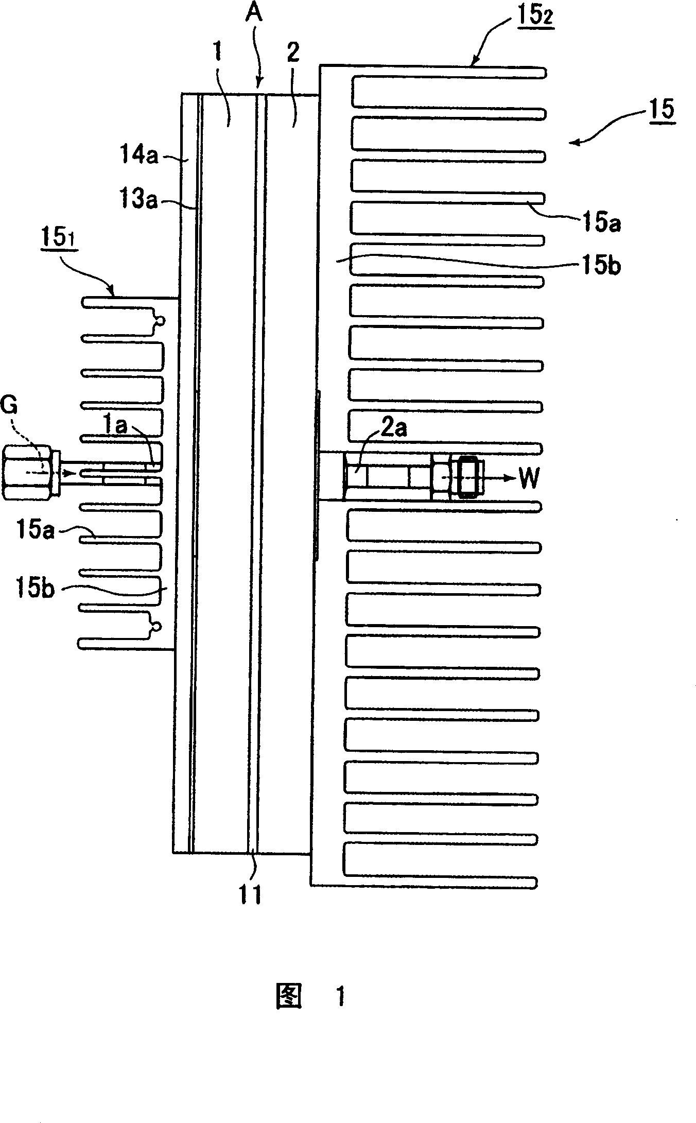
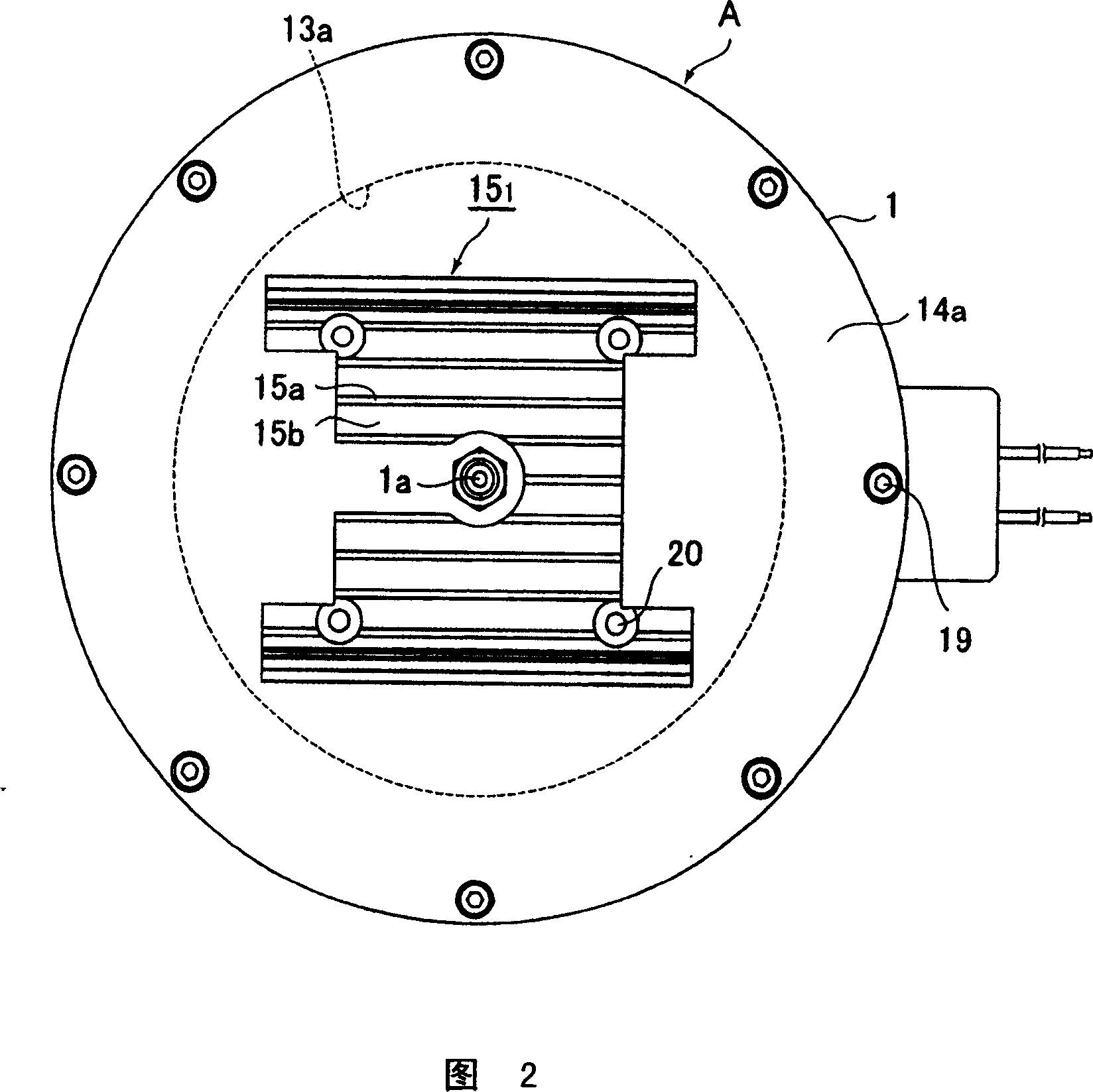
[0099] Among Fig. 1 to Fig. 4, make the external diameter of reaction furnace main body A be 228mmφ, thickness be 37mm, the thickness of internal space V be 17mm, the internal diameter of internal space V be 216mmφ, the thickness of reflector 3a, 3b is 3mm, and profile is 204mmφ, the gap L with the outlet side furnace body part 2 is 1mm, the distance with the inlet side furnace body part 1 is 1mm, the length of the conical surface is about 21mm (inclination angle α=8°), the platinum paint catalyst layer 6 (TiN Barrier coating 7 = 5 μm + pt paint coating 8 = 0.3 μm), and the barrier coatings 9 and 10 on the inner wall surface of the inlet side furnace body part 1 and the outer surfaces of the reflectors 3 a and 3 b are TiN (5 μm).

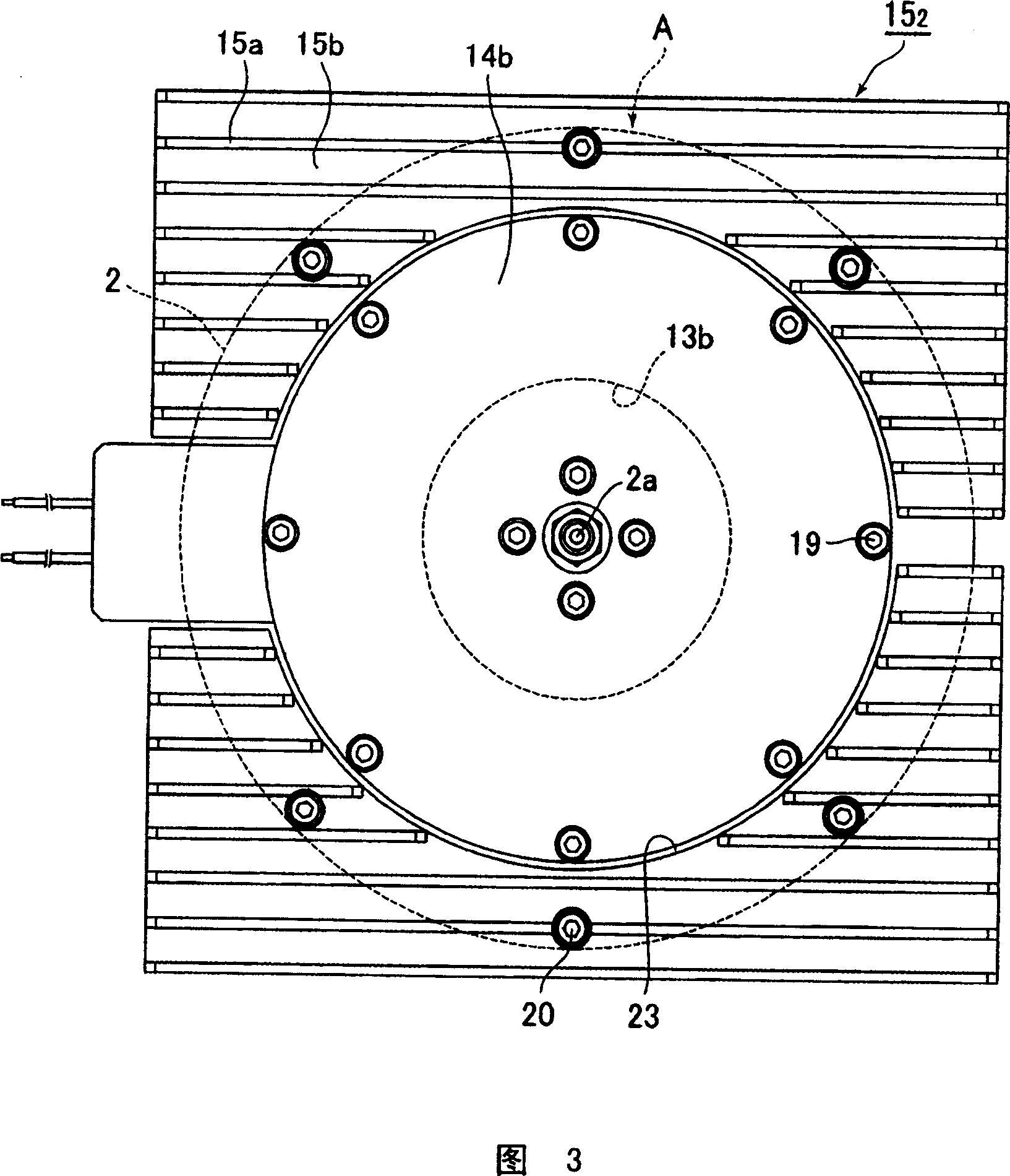
[0100] In addition, let the outer dimensions of the radiator substrate 15b of the cooler 15 be 235×235mm, and the thickness be 10mm, and the outlet side cooler 15 2 The inner diameter of the heater insertion hole 23 is 190mmφ, the height of the cool...

no. 2 Embodiment approach

[0106] Fig. 7 is a longitudinal sectional view of a moisture generating reactor according to a second embodiment of the present invention, Fig. 8 is a plan view thereof, and Fig. 9 is a right side view.

[0107] Referring to Fig. 7 to Fig. 9, the reaction furnace body A for moisture generation is formed by combining the inlet side furnace body part 1 and the outlet side furnace body part 2 of stainless steel (SUS316L) in an opposing shape and welding them in an airtight state. Circular hollow table shape.

[0108] The entrance-side furnace main body member 1 is provided with a circular concave portion with a planar bottom inside, and the gas supply port 1a communicates with the concave portion. In addition, in the outlet-side furnace main body member 2, a circular concave portion having a planar bottom surface is provided inside, and the water vapor outlet 2a communicates with the concave portion. Furthermore, flanges are respectively formed inwardly at the outer peripheral e...

Embodiment 2

[0124] Among Fig. 7 to Fig. 9, make the external diameter of reaction furnace main body A be 228mmφ, thickness be 37mm, the thickness of internal space V be 17mm, the internal diameter of internal space V be 216mmφ, the thickness of reflector 3a, 3b is 3mm, and profile is 204mmφ, the gap L with the outlet side furnace body part 2 is 1mm, the distance with the inlet side furnace body part 1 is 1mm, the length of the conical surface is about 21mm (inclination angle α=8°), the platinum paint catalyst layer 6 (TiN Barrier coating 7 = 5 μm + pt paint coating 8 = 0.3 μm), and the barrier coatings 9 and 10 on the inner wall surface of the inlet side furnace body part 1 and the outer surfaces of the reflectors 3 a and 3 b are TiN (5 μm).

[0125] In addition, let the inlet side cooler 15 1 and outlet side cooler 15 2 The outer dimensions of the radiator substrate 15b are 235×235mm, the thickness is 10mm, and the outlet side cooler 15 2 The inner diameter of the heater insertion hole...


PUM

PropertyMeasurementUnit
volumeaaaaaaaaaa
surface areaaaaaaaaaaa
volumeaaaaaaaaaa

Abstract

A reactor for generating moisture with a limited volumetric capacity for generating moisture capable of safely doubling the generated amount of moisture by increasing the heat radiation characteristic of a reactor body and a feeding apparatus using the reactor. More specifically in the reactor for generating moisture, hydrogen and oxygen fed into the reactor body are brought into contact with a platinum coated catalyst layer to active the reactivity thereof so that the hydrogen and the oxygen are allowed to react with each other under a non-combustion state. A cooler is formed of an outlet side cooler having a heat radiating body substrate with a heater insert hole at a center which is fixed to the outer surface of an outlet side furnace body member and a plurality of heat radiating bodies vertically installed on those portions of the heat radiating body substrate other than the heater insert hole parallel with each other. A part of a heater for heating the reactor body is inserted into the heater insert hole of the outlet side cooler and fixed to the outer surface of the outlet side furnace body member.

Description

technical field [0001] The present invention mainly relates to a reactor for generating moisture used in a semiconductor manufacturing device, and a moisture generating and supplying device using the reactor for generating moisture, used for generating and supplying or removing moisture for forming an oxide film of silicon Treatment of hydrogen discharged from the chamber, etc. Background technique [0002] Conventionally, in semiconductor manufacturing equipment, a reactor for generating moisture having a structure as shown in FIG. 15 has been frequently used. [0003] That is, in Fig. 15, A is the reaction furnace main body, B is the temperature control device, H 2 for hydrogen, O 2 is oxygen, G is mixed gas, W is water vapor, L is gap, V is internal space, α is the inclination angle of the peripheral edge of the reflector, 1 is the main part of the inlet side furnace, 1a is the gas supply port, 2 is the outlet The main part of the side furnace, 2a is the water vapor ou...

Claims


Application Information

Patent Timeline
Patent Type & Authority Applications(China)
IPC IPC(8): C01B5/00
CPCF28F3/02B01J2219/00096B01J12/007F28D2021/0029B01J2219/00135B01J2219/00078C01B5/00B01J2219/00087H01L21/67017B01J12/00
Inventor 成相敏朗川田幸司平尾圭志皆见幸男森本明弘池田信一
Owner FUJIKIN INC
Features
  • R&D
  • Intellectual Property
  • Life Sciences
  • Materials
  • Tech Scout
  • Unparalleled Data Quality
  • Higher Quality Content
  • 60% Fewer Hallucinations
Learn More