
Method for making copper oxygen gun nozzle

A manufacturing method and copper-oxygen technology, applied in the direction of manufacturing converters, etc., can solve the problems of reduced cooling space and effective cooling area, reduced service life, small welding area, etc., to reduce production costs, improve service life, and thermal conductivity. Good results

Inactive Publication Date: 2007-04-25
梁璐
View PDF0 Cites 1 Cited by
  • Summary
  • Abstract
  • Description
  • Claims
  • Application Information

AI Technical Summary

Problems solved by technology

The common feature of the above three structures is that the top of the oxygen lance nozzle and other parts are made of pure copper, which not only increases the production cost, but also increases the thermal resistance at the top of the oxygen lance nozzle, reduces the cooling space and effective cooling area, Reduced cooling intensity and reduced service life
my country's copper resources are poor. According to relevant information, 60% of the copper used in my country's industrial production is imported, and the copper used in my country accounts for 30% of the world's copper. Therefore, the oxygen lance nozzle is made of pure copper, which not only reduces the production cost Increase is also a waste of resources
There is also a structural form of the oxygen lance nozzle that splits the oxygen blowing hole into three sections, one end of the middle section is connected by thread, and the other end is connected by welding. This kind of oxygen lance nozzle has a complicated structure and many connection points and cannot be used in industry. Production
In addition, there is an assembled oxygen lance nozzle, which welds the 90-degree section of the oxygen blowing hole wall perpendicular to the oxygen blowing hole axis. Due to the small welding area, its mechanical strength cannot meet the process requirements, and it cannot form a practical product.

Method used


Image

  • Method for making copper oxygen gun nozzle

Examples


Embodiment Construction

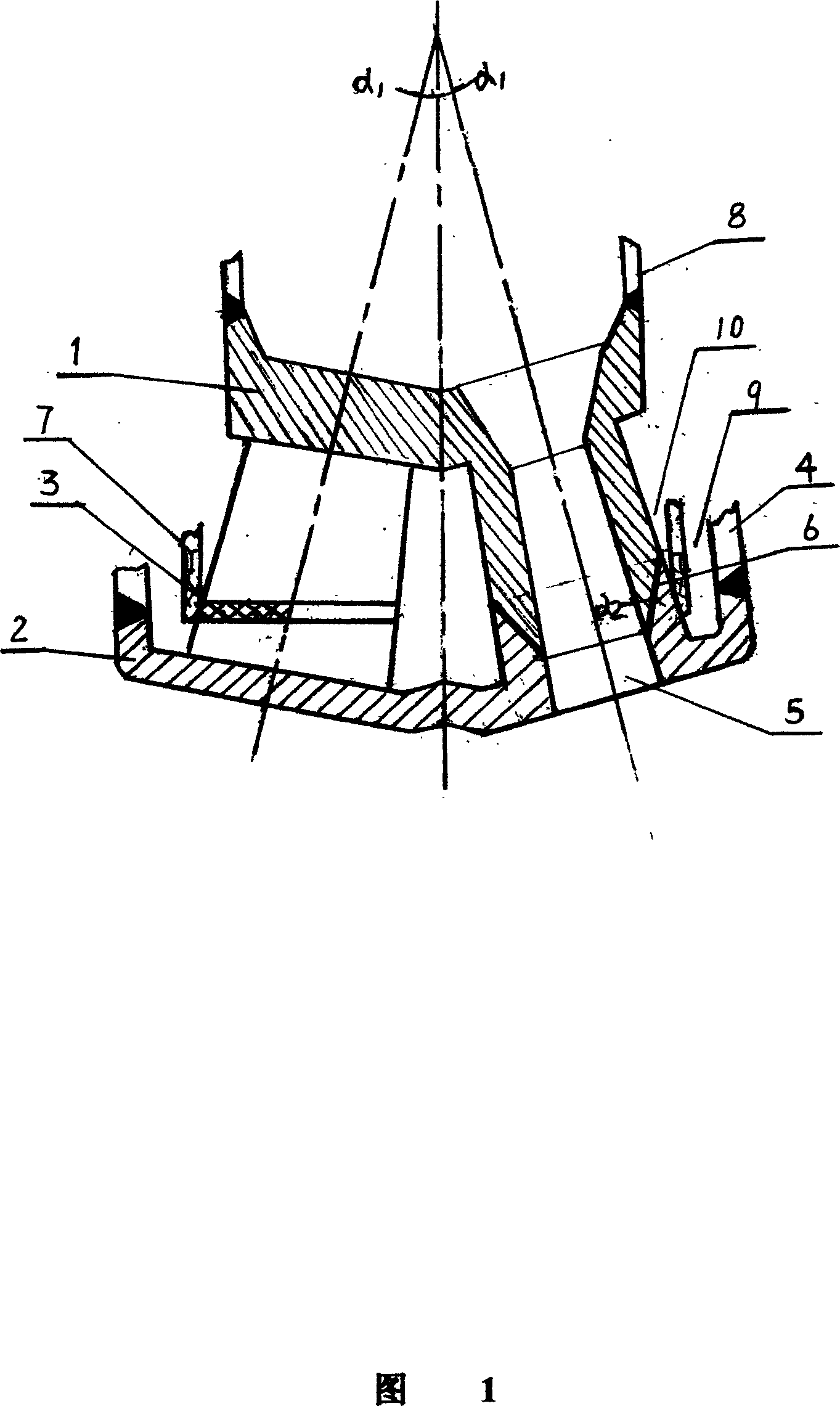
[0010] The manufacturing method of the copper-oxygen lance nozzle of the present invention is realized in this way, which will be described in detail below in conjunction with the accompanying drawings. As shown in Figure 1, the copper-section oxygen lance nozzle is composed of: oxygen inlet end 1, oxygen blowing end 2, water barrier 3, oxygen lance outer tube 4, oxygen blowing hole 5, welding groove 6, oxygen lance middle tube 7, oxygen lance The gun tube 8, the water inlet channel 9, and the water outlet channel 10 are composed. Since the oxygen blowing end 2 has a high temperature when working in the converter and requires high thermal conductivity, the oxygen blowing end is made of copper die forging. Because the oxygen blowing end 1 is soaked In cooling water, the oxygen inlet is made of cast steel, steel or a low cost alloy such as brass. Arrange 3 to 8 oxygen blowing holes 5 in the circumferential direction of the oxygen blowing end 2, and the angle α formed by the axis...


PUM


Abstract

This invention involves a manufacture method for copper-saved oxygen lance nozzle. It is characterized in: copper-saving oxygen lance nozzle comprises the upper oxygen-in-end and the subjacent oxygen blow end, fix 3-8 oxygen blow hole at circumferential direction of the oxygen blow end, the included anglealpha1of oxygen lance nozzle axial ray and the oxygen blow hole is 7- 18degree, water-blocking plate surrounds the lateral wall of oxygen blow hole and connects with oxygen lance tube, the included angle of oxygen lance nozzle axial ray of the connection of the upper oxygen-in-end and the subjacent oxygen blow end and welding slope groove isalpha2,alpha2>= alpha1. The oxygen-in-end of the copper-saved oxygen lance sprayer in this invention adopts cast steel, steel or low-cost alligation such as brass and other materials, which not only improves the service life but also lowers the cost of production and saves copper resources. The invention has the advantages of high mechanical strength, good thermal conductivity, reasonable design and simple structure. The service life of the nozzle is 3 times of cast copper oxygen lance nozzle.the method can save about 50% copper.

Description

technical field [0001] The invention relates to an oxygen lance nozzle, an equipment accessory for converter steelmaking in the metallurgical industry, in particular to a method for manufacturing a copper-saving oxygen lance nozzle. Background technique [0002] Oxygen lance is the key equipment of converter steelmaking, the design, manufacture and usage of its nozzle are particularly important for improving steel output, quality and reducing production cost. The oxygen lance nozzles traditionally used by domestic iron and steel enterprises are made of copper casting, semi-integral extrusion and forging. Oxygen lance nozzles produced by casting have disadvantages such as loose casting structure, many defects and rough inner surface. The common feature of the above three structures is that the top of the oxygen lance nozzle and other parts are made of pure copper, which not only increases the production cost, but also increases the thermal resistance at the top of the oxygen...

Claims


Application Information

Patent Timeline
Patent Type & Authority Applications(China)
IPC IPC(8): C21C5/46
Inventor 梁璐
Owner 梁璐
Learn More