
Open-end spinning apparatus with fiber transport channel consisting of several channel structural components

An open-end, spinning machine technology, applied in open-end spinning machines, continuous winding spinning machines, spinning machines, etc., can solve problems such as unattainable quality, porosity, rough surface of the carded edge, etc., Achieve increased applicability and flexibility, simple interchangeability, and reduced complexity

Inactive Publication Date: 2007-04-25
RIETER INGOLSTADT SPINNEREI
View PDF3 Cites 7 Cited by
  • Summary
  • Abstract
  • Description
  • Claims
  • Application Information

AI Technical Summary

Problems solved by technology

Another disadvantage is that in order to produce large and complex channel parts by powder injection casting, expensive casting molds must first be produced
However, when the edge parts including the carding edge are manufactured by powder injection casting, the surface of the carding edge is often rough and porous, and the required quality is often not achieved

Method used


Image

  • Open-end spinning apparatus with fiber transport channel consisting of several channel structural components
  • Open-end spinning apparatus with fiber transport channel consisting of several channel structural components
  • Open-end spinning apparatus with fiber transport channel consisting of several channel structural components

Examples


Embodiment Construction

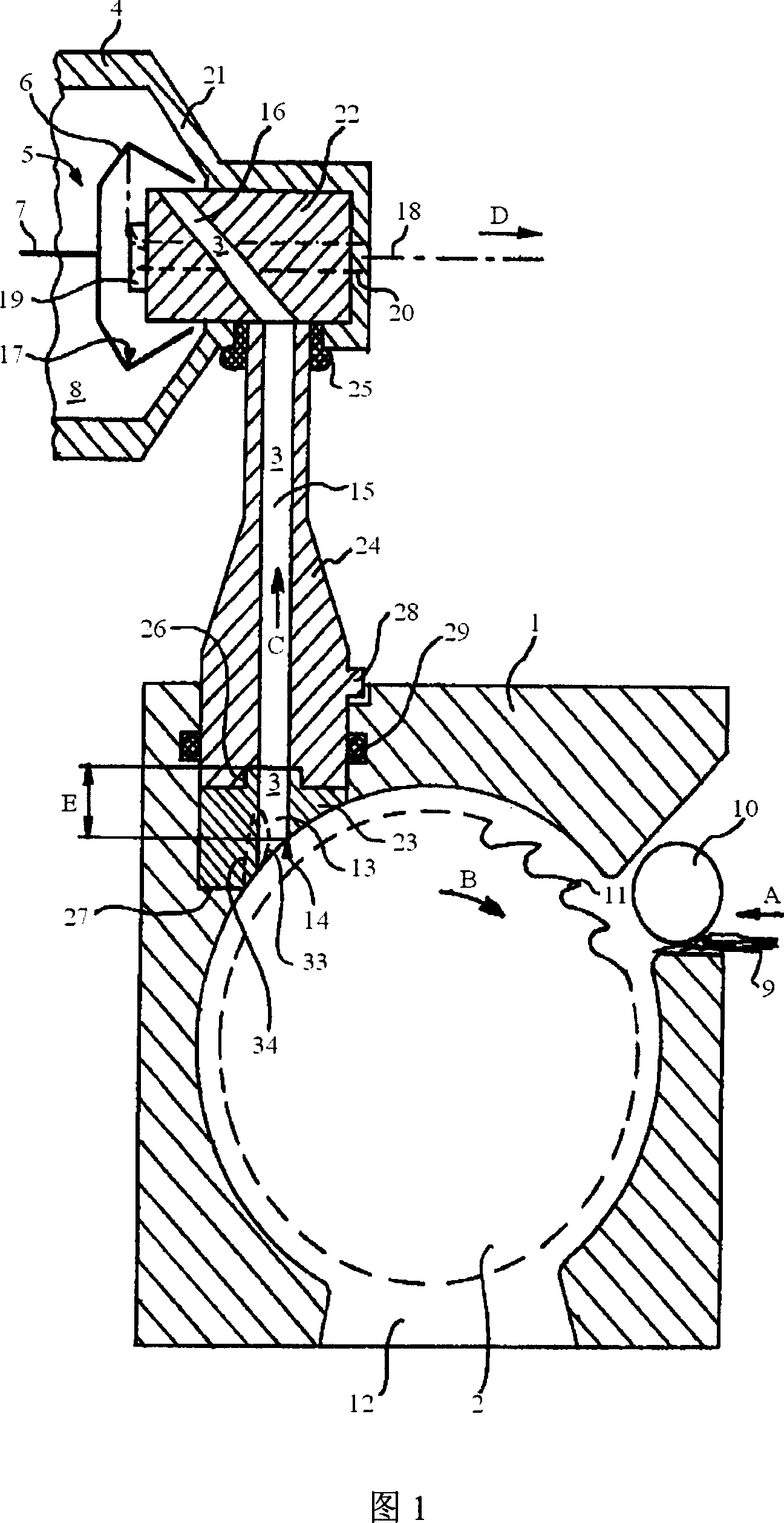
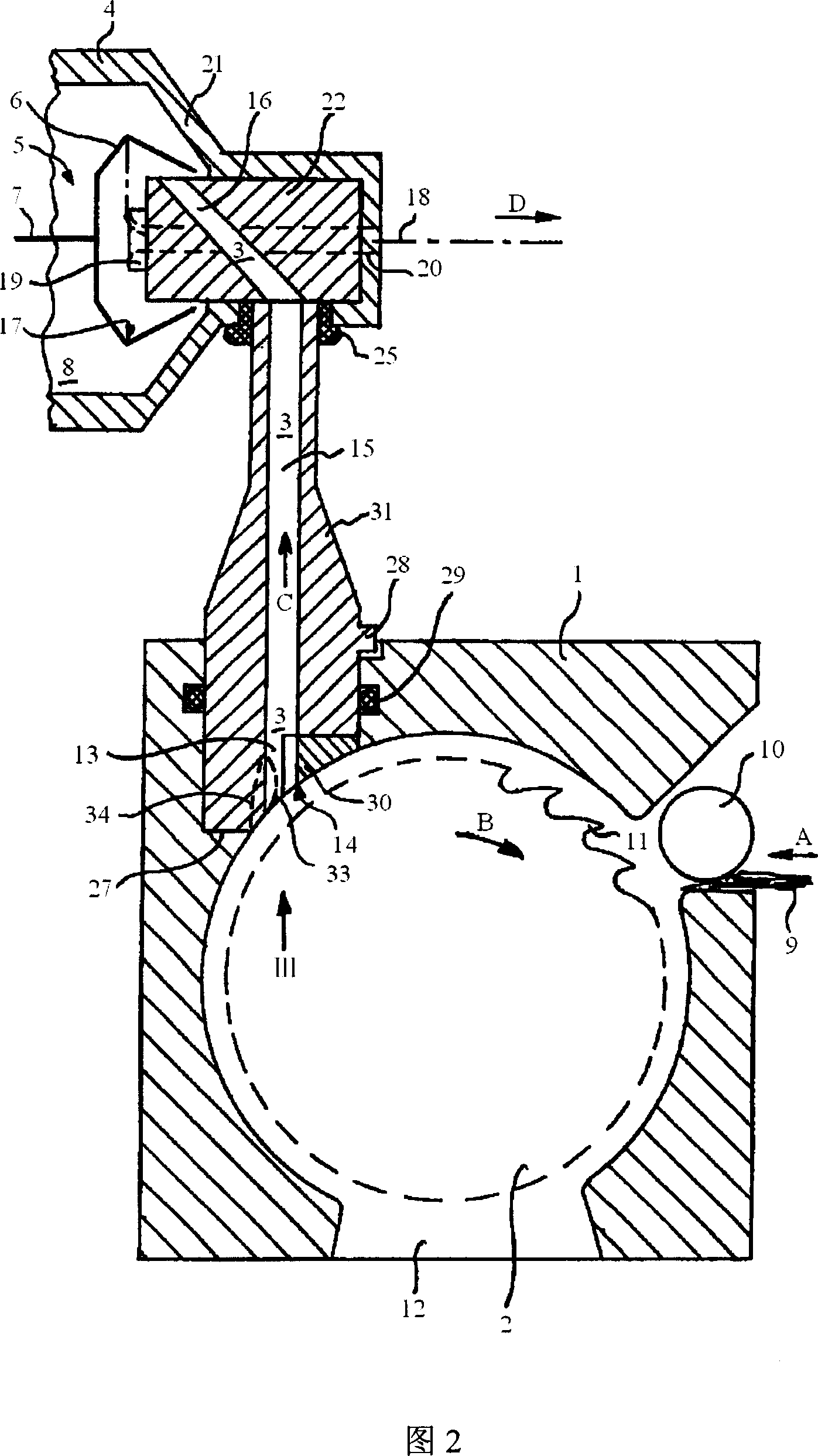
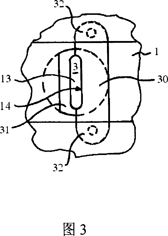
[0023] The open-ended spinning machine shown in FIGS. 1 and 2 comprises, as basic components, a card roll housing 1 with a card roll 2 , a fiber duct 3 and a spinning machine arranged in the rotor housing 4 . Yarn rotor 5. The spinning rotor 5 consists of a turntable 6 and a rod 7 pressed into the turntable. The rod 7 on the spinning rotor 5 and the card roller 2 are positioned and driven in a manner not shown in the figures. During operation, the turntable 6 rotates in the negative pressure chamber 8, and the negative pressure chamber 8 is formed by the rotor housing 4. The rotor housing 4 is connected to a negative pressure source, but the specific way is not shown in the figure.

[0024] The fibrous material is transported in the form of a fiber web 9 via a drivable feed roll 10 in the direction of the arrow A to the carding roll 2 . The fiber strip 9 is carded into finer fibers by the needles or teeth 11 (only schematically shown) arranged on the outer periphery of the ...


PUM


Abstract

The invention describes an open-ended spinning machine with a spinning rotor and a housing with carding rollers. The open-ended spinning machine is equipped with a fiber channel for conveying the fibers from the carding rollers to the spinning rotor, wherein the fiber channel consists of several channel parts arranged relative to one another. The fiber channel is provided with at least one fiber opening edge section, an initial section for receiving the fibers delivered from the carding roll, and a fiber delivery section connected thereto. Install a channel part that can be placed in the carding roll housing and contains the fiber channel transfer part, and an edge part that includes at least the opening edge part, wherein the edge part independently constitutes the starting part of the fiber channel and can be fixedly installed on the channel part superior. Preferably, an edge part that can be placed in the carding roll housing and includes the transfer part is installed, and an edge part that at least includes the opening edge is installed, wherein the edge part can be fixed in the carding roll housing, and the edge part contains the opening of the fiber channel. beginning part.

Description

technical field [0001] The invention relates to an open-ended spinning machine with a spinning rotor and a card roll housing with card rolls and a housing for feeding fibers from the card roll to the spinning machine. A fiber channel of a yarn rotor, wherein the fiber channel consists of several channel parts arranged relative to each other. The fiber channel is provided with at least one fiber opening edge section, an initial section for receiving the fibers delivered from the carding roll, and a fiber delivery section connected thereto. Background technique [0002] In an open-ended spinning machine, the configuration of the fiber channels is decisive for the quality of the jet-spun fibers. Through the fiber channel, the fibers separated by the carding rollers are conveyed to the spinning rotor, where they are collected in the fiber collecting groove of the spinning rotor, and then sucked out from the fiber collecting groove and twisted into a fiber. During the entire pr...

Claims


Application Information

Patent Timeline
IPC IPC(8): D01H4/08
CPCD01H4/30D01H4/38
Inventor M·布尔歇特
Owner RIETER INGOLSTADT SPINNEREI
Learn More