Rotor blade for a wind turbine

A technology of rotor blades and blades, which is applied in the field of reducing the characteristics of noise generation, can solve problems such as high labor cost

Inactive Publication Date: 2007-05-02
NORDEX ENERGY
View PDF3 Cites 5 Cited by
  • Summary
  • Abstract
  • Description
  • Claims
  • Application Information

AI Technical Summary

Problems solved by technology

What all the techniques involved have in common is the considerable labor involved in the way they are manufactured

Method used


Image

  • Rotor blade for a wind turbine
  • Rotor blade for a wind turbine
  • Rotor blade for a wind turbine

Examples


Embodiment Construction

[0019] The same reference numbers are used in all figures.

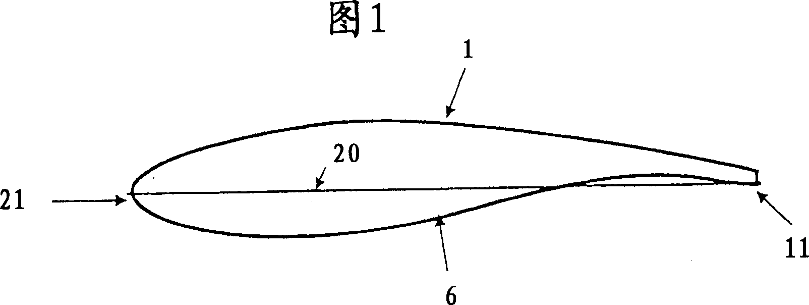
[0020] The rotor blade shown in cross section in FIG. 1 consists of an upper shell 1 and a lower shell 6 . The profile ends at the rear with a profile trailing edge 11 . The leading edge of the profile is defined by the profile nose 21 . The profile chord 20 is also shown in this figure.

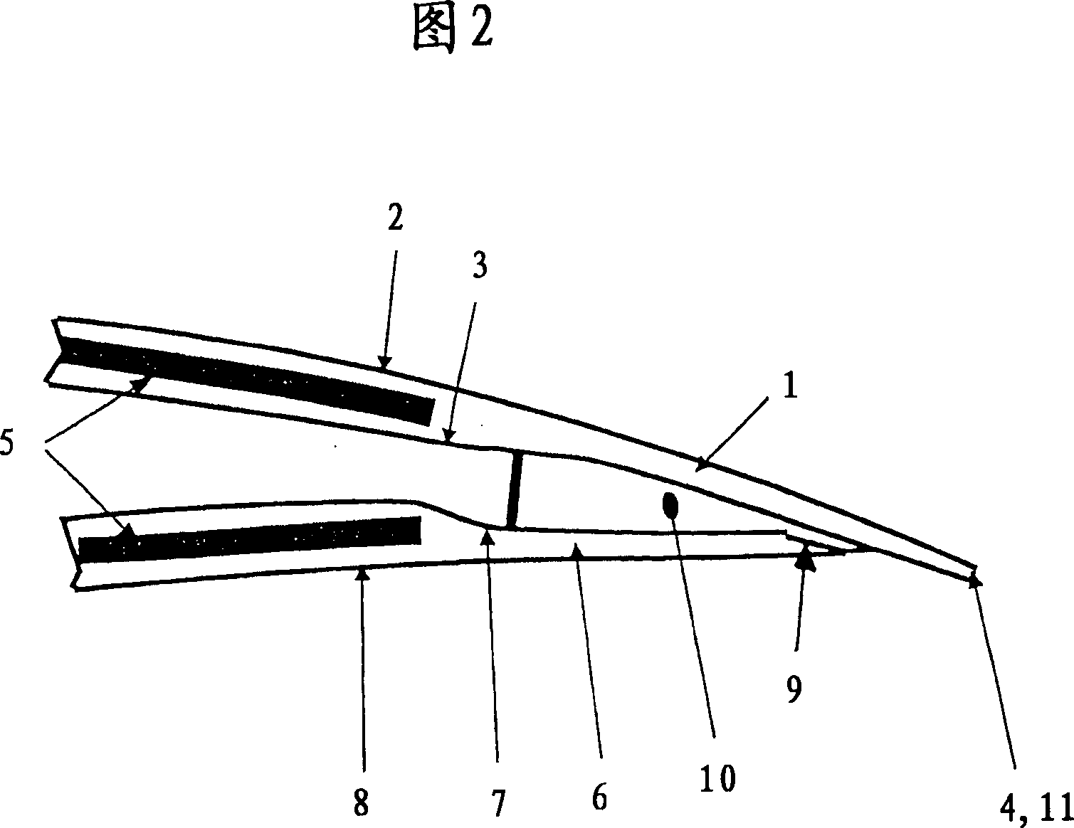
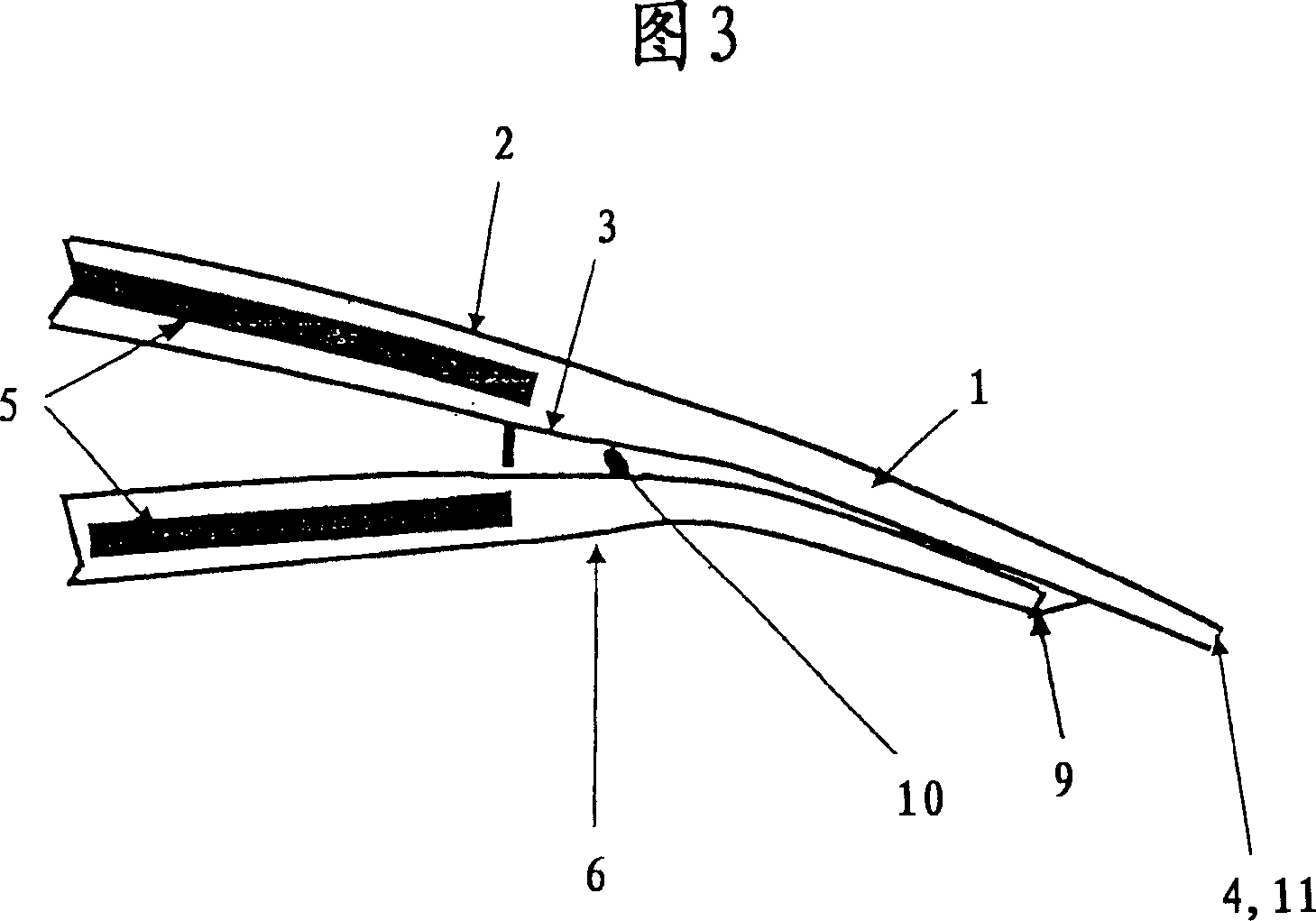
[0021] Figure 4 shows the prior art, showing a cross-section through the trailing edge of the rotor blade. The upper shell 1 has an exterior 2, an interior 3 and a trailing edge 4, and is partially filled with a spacer material 5, such as balsa wood or foam. The same applies to the lower shell 6 , which has an inner 7 , an outer 8 and a rear edge 9 . The area 10 between the two housing halves 1 , 6 is filled with adhesive to join the upper and lower housings 1 , 6 . Both the trailing edges 4 and 9 are consistent with the profile trailing edge 11 . The two trailing edges 4 , 9 define the thickness of the profiled trailing edge...


PUM


Abstract

A rotor blade for a wind power plant, comprises an upper shell and a lower shell which are joined to each other and have a trailing edge each, and which has a profile extending in the direction of flow and, at its rear end, exhibiting a profile trailing edge of a thickness, wherein the trailing edges of the upper and lower shells are spaced apart in at least one area of the rotor blade such that the thickness of the profile trailing edge is defined by one of the shells.

Description

technical field [0001] The invention relates to a rotor blade of a wind power plant by means of which particularly advantageous properties, in particular reduced noise generation, can be achieved in a simple manner. Background technique [0002] Traditionally, the rotor blades of wind power plants consist of fiber-reinforced plastics. During this manufacturing process, the upper shell and the lower shell are initially produced from fiber-reinforced plastic and subsequently adhered to each other at least in the region of the leading edge and the trailing edge. This type of construction makes it possible to produce rotor blades of light and strong construction, which can be freely selected within a wide range. [0003] But this raises a problem of the noise that is inherent in the operation of wind power plants. To a large extent, this operating noise comes from wind noise, which is generated around the trailing edge of the rotor blades, where the air volumes flowing along t...

Claims


Application Information

Patent Timeline
Patent Type & Authority Applications(China)
IPC IPC(8): F03D11/00
CPCF05B2260/96F03D1/0633F05B2240/30Y02E10/721Y02E10/72
Inventor H·罗赫霍尔茨
Owner NORDEX ENERGY
Why Eureka
Try Eureka