Dehumidifier

A dehumidifier and blower technology, which is used in household heating, lighting and heating equipment, space heating and ventilation, etc., can solve the problems of increasing the number of mold investment and assembly processes, loosening and falling off, and increasing production costs. The effect of reducing the assembly process, good safety, and reducing production costs

Inactive Publication Date: 2007-05-02
LG ELECTRONICS (TIANJIN) APPLIANCES CO LTD
View PDF0 Cites 4 Cited by
  • Summary
  • Abstract
  • Description
  • Claims
  • Application Information

AI Technical Summary

Problems solved by technology

But, there is following problem in this dehumidifier of prior art: because orifice plate 68 and motor support 72 utilize two sets of independent molds to be assembled after making, then utilize fixing device to be positioned at motor support 72 middle parts from two The motor 75 is fixedly arranged on the back side of the motor bracket 72 by the fixing hole 73, which will not only increase the investment of the mold and the number of assembling operations, thereby increasing the production cost, but also make the motor 75 in the motor 75 when the two-point method is used to fix the motor 75. Easy to loosen and fall off during operation

Method used


Image

  • Dehumidifier
  • Dehumidifier

Examples


Embodiment Construction

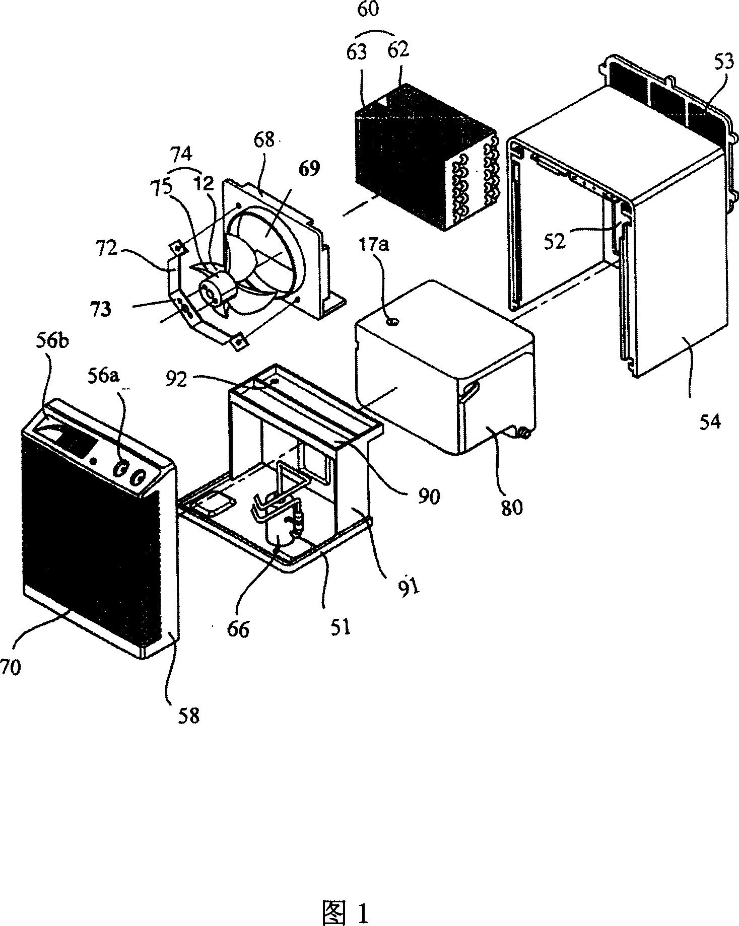
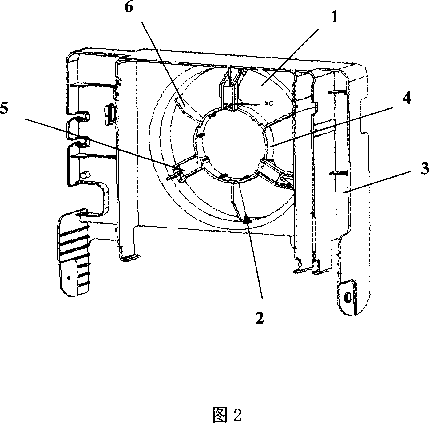
[0011] As shown in Fig. 2 and Fig. 1, the dehumidifier provided by the present invention includes a chassis 51 constituting the external structure of the bottom surface; constituting the external structure of the top surface and two sides, and a box body 54 formed with an air inlet 52 on the back; constituting the front surface The outer structure, and the lower part of the front face is formed with an exhaust port 70, and the upper part is installed with the front panel 58 of the operation part 56a and the display part 56b; it is installed on the air inlet 52 of the box body 54 to filter out the inhaled air The air filter 53 of mixed impurities; it is arranged at the inner front end of the casing 54, and is composed of a motor 75 and a blower fan 12, and is used for a blower 74 for forced circulation of indoor air; it is arranged at the inner rear end of the casing 54, and is composed of an evaporator 62 and a condenser 63, a heat exchanger 60 for heat exchange with indoor air...


PUM


Abstract

A dehumidifier consists of a chassis for forming bottom, top and two side panel for forming cabinet, panel for forming front surface, an air filter sets at back panel of cabinet, a blower sets at internal of cabinet,a heat exchanger formed by evaporator and condenser, compressor, condensed water tray, baffle, water groove, airflow guide hole set between said blower and said heat exchanger for guiding airflow and motor support orifice plate being formed in integral way at internal of airflow guide hole.

Description

technical field [0001] The invention relates to a dehumidifier, in particular to a dehumidifier capable of reducing production costs, reducing assembly procedures and having good safety. Background technique [0002] Generally speaking, a dehumidifier is a kind of air that can suck indoor humid air into its box, and then discharge it to the room after reducing the humidity through a heat exchanger composed of a condenser and an evaporator with a refrigerant flowing inside, thereby reducing the humidity. A device for indoor air humidity. Fig. 1 is an exploded perspective view of a dehumidifier in the prior art. As shown in Figure 1, this prior art dehumidifier mainly includes: a chassis 51 constituting the external structure of the bottom surface of the dehumidifier; a box forming the top surface and two side external structures of the dehumidifier, and an air inlet 52 is formed on the back. body 54; constitute the front external structure of the dehumidifier, and the lower...

Claims


Application Information

Patent Timeline
IPC IPC(8): F24F3/14F24F1/02
Inventor 张可
Owner LG ELECTRONICS (TIANJIN) APPLIANCES CO LTD
Why Eureka
Try Eureka