Ring-shape laser magnetometer

A magnetometer and laser gain technology, applied in instruments, scientific instruments, electric/magnetic exploration, etc., can solve the problems of low precision and stability of magnetometer, difficulty in improving sensitivity, etc.

Inactive Publication Date: 2007-05-02
李贵祥
View PDF0 Cites 5 Cited by
  • Summary
  • Abstract
  • Description
  • Claims
  • Application Information

AI Technical Summary

Problems solved by technology

The accuracy and stability of these two component magnetometers are not high, and it is difficult to improve the sensitivity

Method used


Image

  • Ring-shape laser magnetometer
  • Ring-shape laser magnetometer

Examples


Embodiment Construction

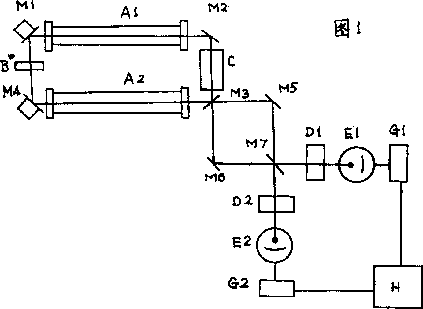
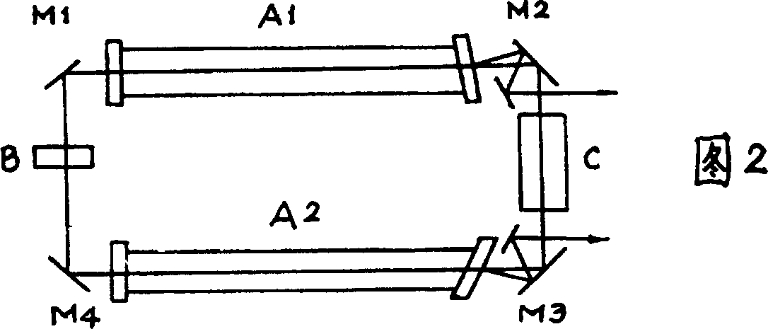
[0019] 1. In order to stabilize the length of the laser resonator, the two-angle reflector is fixed on a glass-ceramic block, and the other two-angle reflectors are attached to the piezoelectric ceramic first, and then the piezoelectric ceramic is fixed on the above-mentioned glass-ceramic block, and The above-mentioned two corner reflectors form a rectangular laser resonant cavity. A variable voltage is applied to the piezoelectric ceramic, so that the voltage controls the elongation and shortening of the piezoelectric ceramic to stabilize the change of the length of the resonant cavity caused by the change of the ambient temperature. The magnitude of the voltage is given by the frequency stabilization method of the light intensity difference between the left-handed circular polarized light and the right-handed circular polarized light in a closed circuit.

[0020] 2. All corner reflectors are made of hard dielectric film. In order to eliminate the ellipticity of the circula...


PUM


Abstract

A laser magnetometer of ring form is prepared as setting Faraday magneto-optic material to be rectangular form, utilizing two gain tubes being set with the same parameter and being set symmetrically to provide light amplification and to overcome Zeeman effect, applying crystal quarts to generate component on internal light path of Faraday magneto-optic material in circular polarization light laser and applying flint glass in length of several mm and thickness of a dozen mm as Faraday magneto-optic material.

Description

technical field [0001] The invention belongs to a measuring instrument for weak magnetic field and earth magnetic field component. Background technique [0002] Magnetometers are widely used in geology, geophysics, military and other departments. Current component magnetometers mainly include fluxgate magnetometers and magnetic scales. The former consists of a permalloy ring (or rod) surrounded by two asymmetric coils, and measures the geomagnetic field by the harmonics of the induced electromotive force. The magnetic balance consists of a piece of ferromagnetic material, and the magnitude of the force on the material in the earth's magnetic field is used to detect the magnitude of the earth's magnetic field. The accuracy and stability of these two component magnetometers are not high, and it is difficult to improve the sensitivity. Contents of the invention [0003] The purpose of the present invention is to manufacture a component magnetometer with high stability or h...

Claims


Application Information

Patent Timeline
Patent Type & Authority Applications(China)
IPC IPC(8): G01V3/00
Inventor 李贵祥
Owner 李贵祥
Why Eureka
Try Eureka