
Process for manufacturing bimetal compound casting liner plate

A technology of compound casting and production process, which is applied in the field of bimetallic composite liners, can solve problems such as difficult to meet, and achieve the effects of low production cost, high service life and simple production process

Inactive Publication Date: 2007-05-16
郭继伟
View PDF0 Cites 27 Cited by
  • Summary
  • Abstract
  • Description
  • Claims
  • Application Information

AI Technical Summary

Problems solved by technology

At present, the materials used for ball mill liners are mainly high manganese steel, alloy cast iron, low alloy steel, etc. It is often difficult for a single material to meet the requirements of working conditions with a wide stress range.

Method used


Image

  • Process for manufacturing bimetal compound casting liner plate

Examples


Embodiment Construction

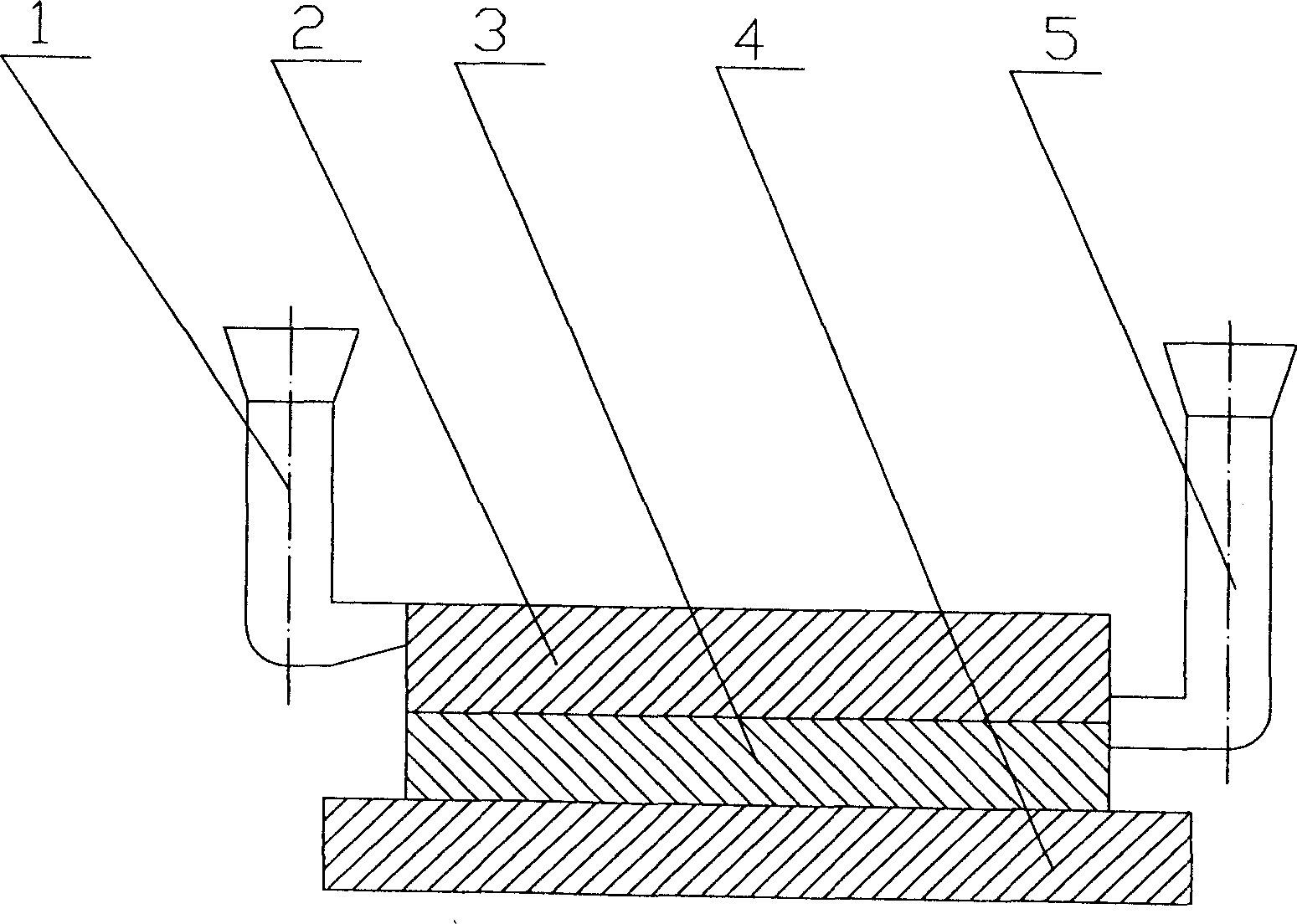
[0009] When pouring, put the working layer upwards, set the chilling material (4) under the cavity, and pour a certain amount of liquid metal of medium-carbon low-alloy bainite wear-resistant steel from the gate (5) at a relatively fast speed, so that It becomes the tougher liner (3). After an interval of 2 to 60 seconds, the liquid metal of high-carbon and low-alloy bainite wear-resistant steel is poured from the pouring riser (1) to make it a wear-resistant layer (2) with high wear resistance. The diameter of the pouring riser (1) should be larger, so that it has a better feeding effect. Heat the cleaned liner to 860~920C 0 , keep warm for 40-100 minutes, then put it into 280-350C 0 The nitrate solution isothermally quenched, and the liner can be taken out after 60 to 120 minutes.


PUM


Abstract

The invention puts cold material in the lower part of casting section, then pours medium carbon low-alloy bainite abrasion resistant liquid metal in to liner; pours high carbon low-alloy bainite abrasion resistant liquid into work layer to cast liner plate; cleaning casting element and quenching at constant temperature, to form the work surface as high-rigid high carbon low-alloy bainite abrasion resistant layer, liner as high-flexibility medim carbon low-alloy bainite abrasion resistant steel. The invention has low cost and long service life.

Description

Technical field [0001] The invention relates to a production process method of a bimetallic composite casting liner, in particular to a bimetallic composite liner cast by a double casting process. Background technique: [0002] Ball mills used in industries such as electric power, building materials, and metallurgy consume a large amount of wearing parts such as grinding balls and liners. During the grinding process, there is relative sliding and rolling between the grinding ball and the liner. In addition to being subjected to repeated impacts, cutting grooves, furrows and extrusion pits are also generated on the surface. The higher the hardness of the material, the worse the crushability, and the more severe the chiseling and extrusion. The larger the diameter of the ball mill cylinder, the greater the impact on the liner. Therefore, the liner is mainly subject to high-stress grinding and impact, which is plastic deformation and abrasive wear. Therefore, it is required ...

Claims


Application Information

Patent Timeline
IPC IPC(8): B22D19/16
Inventor 郭继伟荣守范沈大东
Owner 郭继伟
Learn More