Probe card capable of replacing electron accessory rapidly

A technology for electronic parts and probe cards, applied in the field of probe cards, can solve problems such as time-consuming operation, electrical offset of probe cards, and unreliability

Inactive Publication Date: 2007-05-16
MPI CORP
View PDF0 Cites 8 Cited by
  • Summary
  • Abstract
  • Description
  • Claims
  • Application Information

AI Technical Summary

Problems solved by technology

[0002] The electronic components on the existing probe card, such as passive components such as resistors and capacitors, are fixed on the circuit board by soldering their conductive parts or metal pins, and other components in the circuit are easily damaged due to high welding temperature. The impact of high temperature changes the original characteristics of the components, indirectly leads to the electrical deviation of the probe card, and makes the probe card lose its proper accuracy and reliability when used for electrical measurement.
[0003] In addition, the temperature of the probe card will rise due to the heat consumption in the circuit after a long time of use. Therefore, the characteristics of the electronic parts will inevitably shift after repeated measurements and use, which also makes the probe card used for electrical The proper accuracy and reliability are lost during measurement; especially, when measuring electronic components with probe cards, it is not only for electrical measurement operations under normal voltage or temperature conditions, but also often needs to test electronic components at high and low temperatures or high voltage, current operating characteristics, and even do destructive testing under impact (stress) such as temperature rise or boost, so that the electronic components on the probe card can also operate under harsh test conditions, greatly reducing these The durability of electronic parts (lifetime), so the electronic parts on the probe card need to be updated frequently to maintain the accuracy of the electrical measurement; however, the way to replace the electronic parts is to replace the entire probe card, but to solder on the The electronic parts on the probe card are first desoldered and then re-soldered with new parts, which not only faces the above-mentioned shortcomings of high-temperature soldering, but also requires time-consuming and unreliable re-soldering operations.

Method used


Image

  • Probe card capable of replacing electron accessory rapidly
  • Probe card capable of replacing electron accessory rapidly
  • Probe card capable of replacing electron accessory rapidly

Examples


Embodiment Construction

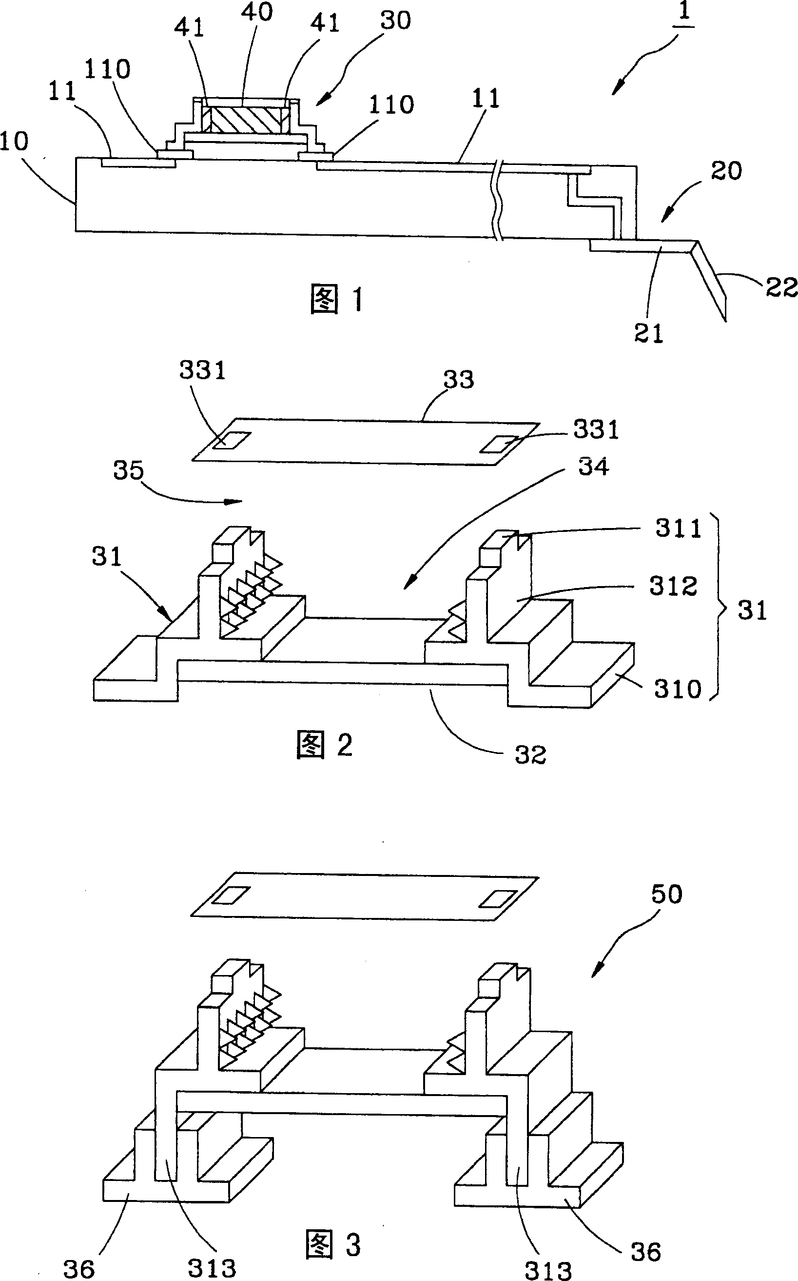
[0040] Please refer to the first preferred embodiment provided by the present invention shown in Fig. 1, which is a device schematic diagram of a probe card 1, which has a circuit board 10, a plurality of probes 20, a plurality of accommodating seats 30 and each of the accommodating Each electronic component 40 that is set in the seat 30, wherein:

[0041] The circuit board 10 is arranged with an electronic circuit 11 , and the layout of the electronic circuit 11 has a plurality of electrical nodes 110 for electrically connecting any passive components such as resistors, capacitors or inductors.

[0042] Each of the probes 20 includes a seat 21 and a needle 22, the electronic circuit 11 is electrically connected to the needle 22 through each seat 21, so that the probe card 1 can connect each of the needles 22 to the component to be tested (Fig. (not shown in the figure), and through the electronic circuit 11 and the measuring machine (not shown in the figure) are electrically ...


PUM


Abstract

This invention relates to rapid update electron parts probe card, which comprises one circuit board, multiple probes and several container sockets, wherein, the circuit board is set with electron circuit connected to the passive elements joints; detect probes is connected to electrical circuit; probe card is to test by detector; each container socket is set with two conductive fix parts on the points to form one container part and at least on open; the container parts are to contain above passive element to connect two fix parts through open to transfer each passive element.

Description

technical field [0001] The present invention relates to a probe card, in particular to a probe card which facilitates the replacement of electronic parts. Background technique [0002] The electronic components on the existing probe card, such as passive components such as resistors and capacitors, are fixed on the circuit board by soldering their conductive parts or metal pins, and other components in the circuit are easily damaged due to high welding temperature. The impact of high temperature changes the original characteristics of the components, indirectly leads to the electrical deviation of the probe card, and makes the probe card lose its proper accuracy and reliability when used for electrical measurement. [0003] In addition, the temperature of the probe card will rise due to the heat consumption in the circuit after a long time of use. Therefore, the characteristics of the electronic parts will inevitably shift after repeated measurements and use, which also make...

Claims


Application Information

Patent Timeline
Patent Type & Authority Applications(China)
IPC IPC(8): G01R1/02G01R1/073G01R31/00
Inventor 顾伟正
Owner MPI CORP
Why Eureka
Try Eureka