Top luminescent type organic LED display device

A technology for light-emitting diodes and display devices, which is applied to electroluminescent light sources, lighting devices, light sources, etc., can solve problems such as reducing the high resistance of driving signals

Inactive Publication Date: 2007-05-16
RITDISPLAY
View PDF1 Cites 9 Cited by
  • Summary
  • Abstract
  • Description
  • Claims
  • Application Information

AI Technical Summary

Problems solved by technology

However, the adhesive layer cannot be used as an auxiliary electrode layer, which can effect...

Method used


Image

  • Top luminescent type organic LED display device
  • Top luminescent type organic LED display device
  • Top luminescent type organic LED display device

Examples


Embodiment Construction

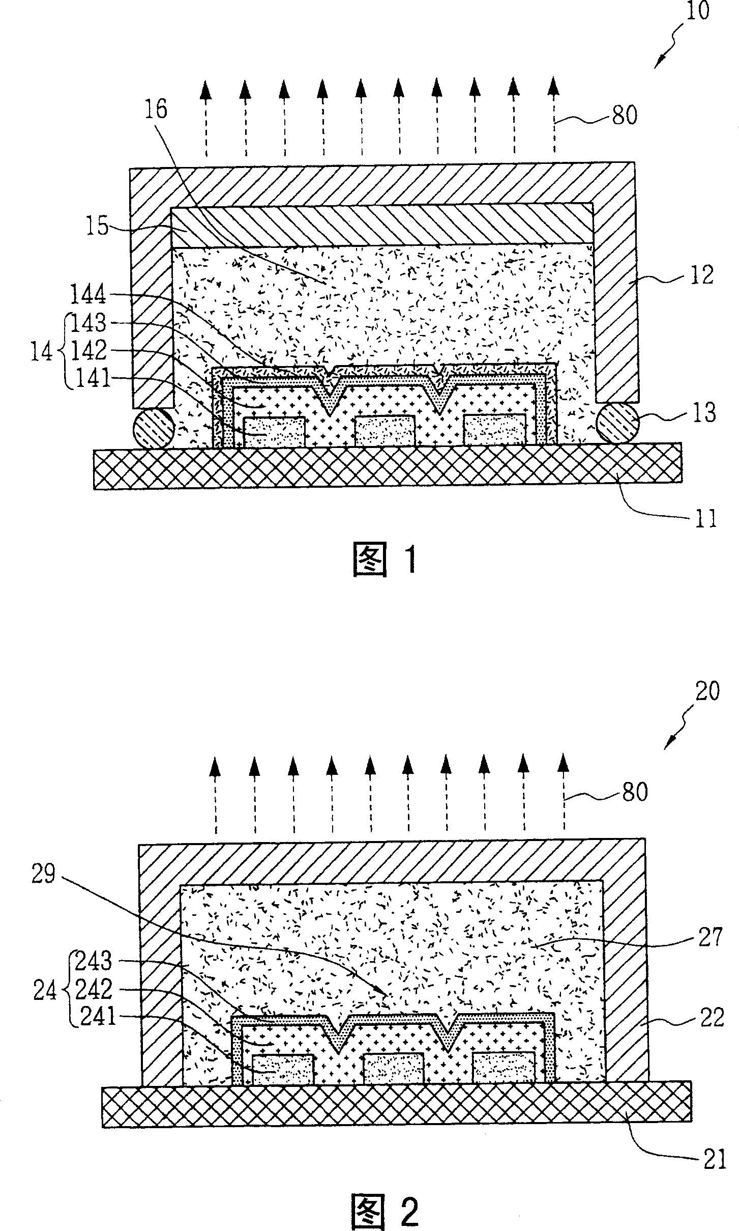
[0047]FIG. 2 is a schematic cross-sectional view of a top emission organic light emitting diode display device according to a first embodiment of the present invention. The top emission organic light emitting diode display device 20 mainly includes a substrate 21, an organic light emitting diode area 29, a conductive transparent filling material 27 and a top cover 22, wherein the substrate 21 and the top cover 22 pass through the conductive transparent The adhesive force of the filling material 27 is combined with each other. The organic light emitting diode region 29 includes at least one organic light emitting diode 24 , and an anode 241 , a light emitting layer 242 and a transparent cathode 243 are sequentially formed on the substrate 21 . In order to allow light to pass through, the transparent cathode 243 is mostly made of relatively thin (less than 50 Angstroms (A)) metal film, but this will increase the resistance of the transparent cathode 243 and reduce electron mobil...


PUM

PropertyMeasurementUnit
Resistivityaaaaaaaaaa

Abstract

The related organic LED display comprises: a substrate, an organic LED with at least an anode and a luminescent layer and a transparent cathode, and the transparent conductive filling material on cathode surface. Wherein, the refraction coefficient of filling material is almost same as the cathode. Thereby, this invention can reduce the rate of light total reflected into the cathode, and decreases drive voltage on cathode.

Description

technical field [0001] The present invention relates to a top-emission organic light emitting diode (ORGANIC LIGHTEMITTING DEVICE; OLED) display device, in particular to an organic light emitting diode display device with a structure that increases light utilization efficiency. Background technique [0002] The light-emitting principle adopted by the organic light-emitting diode display device is different from the current popular liquid crystal display technology in which liquid crystal is used as the light switching medium. The basic structure of an OLED is that an organic phosphor is interposed between two layers of electrodes, and the phosphor generates light by itself after an appropriate voltage is applied. Therefore, there is no need for an external backlight source, so that the organic light emitting diode display device can independently display pictures and texts with a thin structure. [0003] Currently, OLED display devices can be classified into two types of li...

Claims


Application Information

Patent Timeline
IPC IPC(8): H01L51/50H01L51/54H01L51/52H05B33/12H05B33/02
Inventor 徐玉女陈建兴黄俐恬
Owner RITDISPLAY
Why Eureka
Try Eureka