
An amplifier for analog-digital converter

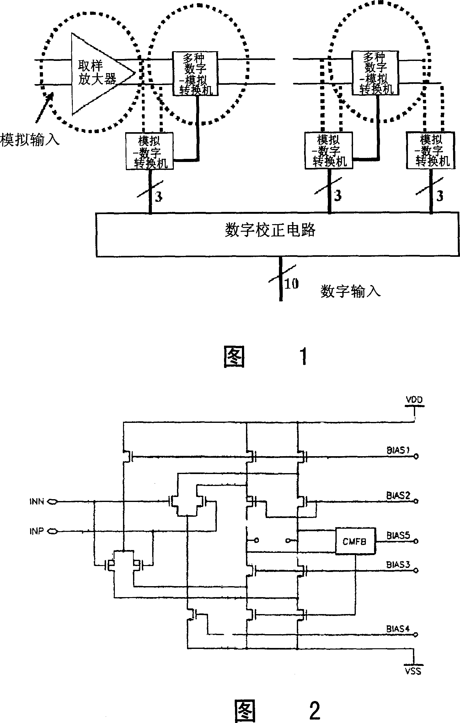
A technology for analog-to-digital converters and amplifiers, which can be used in analog-to-digital converters, DC-coupled DC amplifiers, differential amplifiers, etc., and can solve problems such as unsuitable structures

Inactive Publication Date: 2007-05-16
LEJIN GUANGDIAN ELECTRONIC CO LTD SHANGHAI
View PDF0 Cites 5 Cited by
  • Summary
  • Abstract
  • Description
  • Claims
  • Application Information

AI Technical Summary

Problems solved by technology

If the above-mentioned power supply pole is very low, it is not suitable for the existing equipment structure

Method used


Image

  • An amplifier for analog-digital converter
  • An amplifier for analog-digital converter

Examples


Embodiment Construction

[0023] Hereinafter, the present invention will be described in more detail with reference to the accompanying drawings.

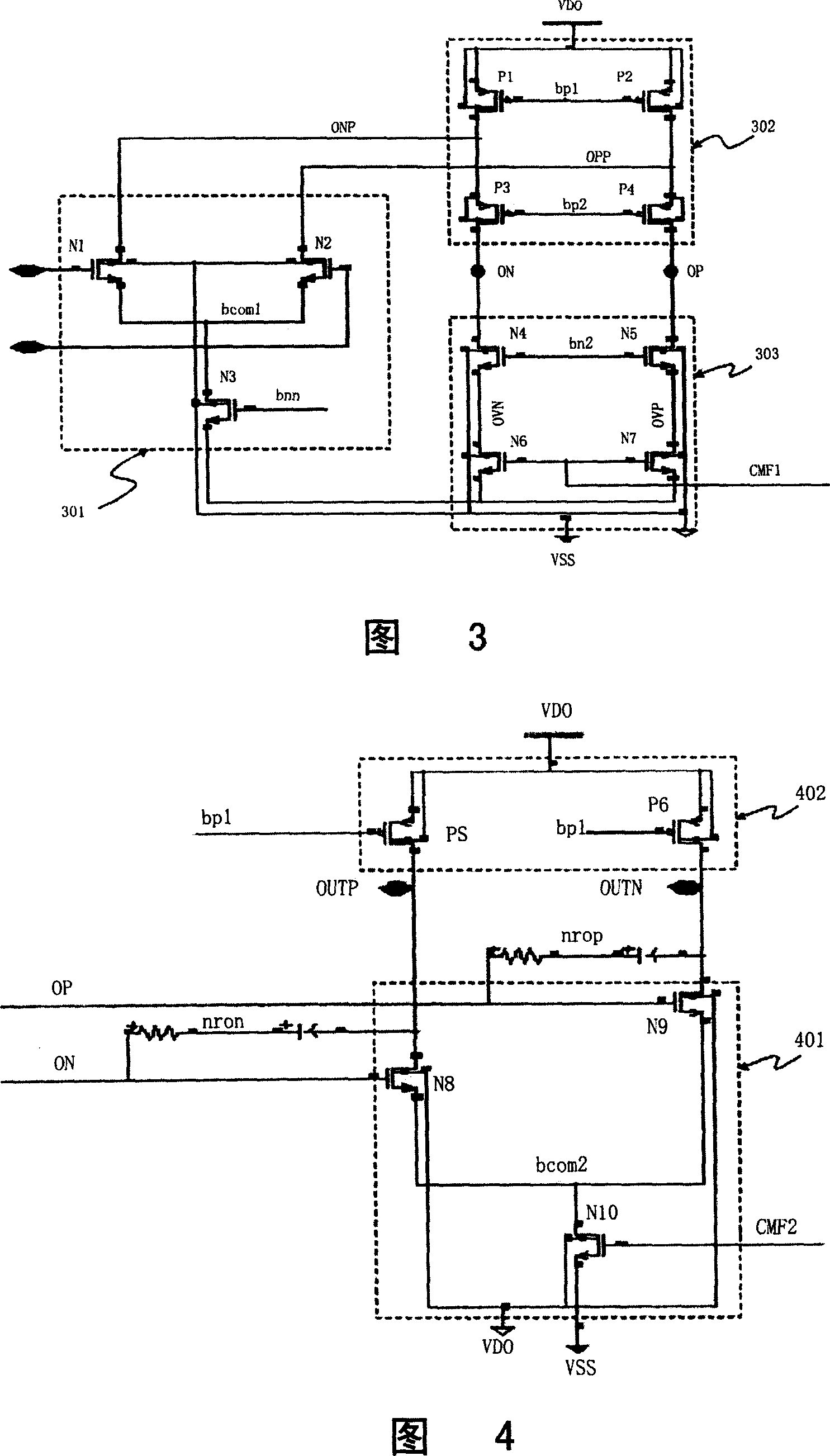
[0024] FIG. 3 is a circuit diagram of a first amplifying part in an amplifier in an analog-to-digital converter according to an embodiment of the present invention.

[0025] In the above embodiments, the first amplifying part of the amplifier includes a first differential input part 301, a cascode current mirror 302, a cascode current source 303 and a bias circuit (not shown in the figure).

[0026] The above-described embodiments are capable of obtaining a high gain with respect to an input signal.

[0027] As shown in FIG. 3, the first amplifying section embodies one circuit as an N-channel input section and a P-channel input section.

[0028] The above-mentioned first differential input part 301 also includes a first NMOS transistor to a third NMOS transistor (N1- - N3). The gate of the first NMOS transistor N1 and the gate of the second NMOS transist...


PUM


Abstract

The related amplifier for ADC comprises: a first differential input part, a cascade current mirror between the output of last part and a first reference potential, a first amplification part for cascade current source between the first input part and a second reference potential, a second differential input part connected with the first input part, and a second amplification part of a second current magnetic mirror.

Description

【Technical field】 [0001] This invention relates to amplifiers for analog-to-digital converters. More specifically, it relates to low voltage, high input range, and high gain amplifiers for analog-to-digital converters used in the mass production of VSB / QAM for digital TV reception. 【Background technique】 [0002] Recently, the digital TV market has a trend of rapid development, and various functions of digital TV have been added because chips with millions of gates or more are used. If the function of the VSB method using the over-the-air digital television reception method is also added, the chip size will increase geometrically. [0003] Therefore, in order to reduce the size of the chip, use (0.35um=>0.18) because it can reduce the current process. However, the reduction of this process, the effect of reducing the size of the digital circuit is very obvious, and at the same time it is very unfavorable for the analog circuit. Working with analog circuits can be very ...

Claims


Application Information

Patent Timeline
IPC IPC(8): H03F3/45H03M1/12
Inventor 李宇烈
Owner LEJIN GUANGDIAN ELECTRONIC CO LTD SHANGHAI
Learn More