

Software radio-based OFDM transmitting and receiving machine able to upgrade
A software radio and transceiver technology, applied in the field of OFDM transceivers, can solve problems such as lack of effective communication, and achieve the effect of easy application and simple structure
- Summary
- Abstract
- Description
- Claims
- Application Information
AI Technical Summary
Problems solved by technology
Method used
Image

Examples
Embodiment
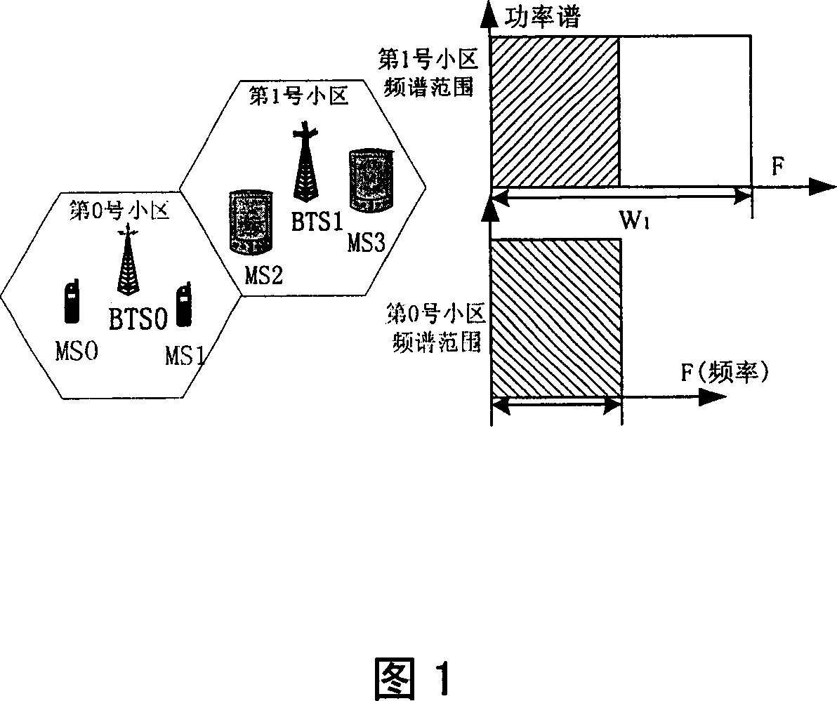
[0046] 1) Transmission of user signals in a new type of transceiver in a broadband cell
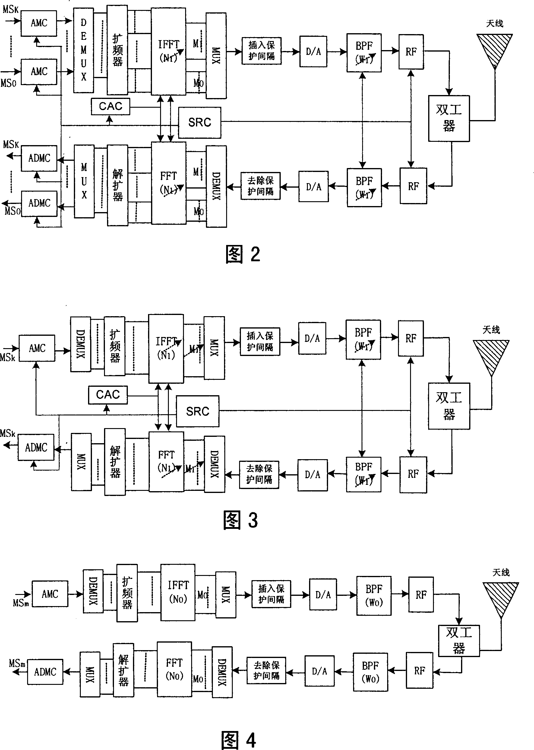
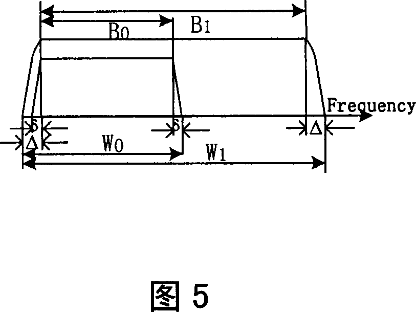
[0047] When a mobile subscriber MS with a new type of transceiver 3 and MS 2 When transmitting data in a broadband cell, its coded and modulated symbol series b 3 and b 2 (Length is L b 3 , L b 2 ) are mapped to M 1 (01 1 , 0b 3 +L b 2 ≤M 1 ) in different subcarriers. After IFFT processing, the baseband output signal of the base station is
[0048] s l ( t ) = 1 T - T cp { Σ k = 0 ...
PUM
 Abstract
Description
Claims
Application Information