

HIFU tumour ablation system
A tumor and treatment device technology, applied in the field of tumor treatment, can solve the problems of high manufacturing cost, complicated operation, system expansion, etc., and achieve the effects of low manufacturing cost and convenient use.
- Summary
- Abstract
- Description
- Claims
- Application Information
AI Technical Summary
Problems solved by technology
Method used
Image

Examples
Embodiment 1
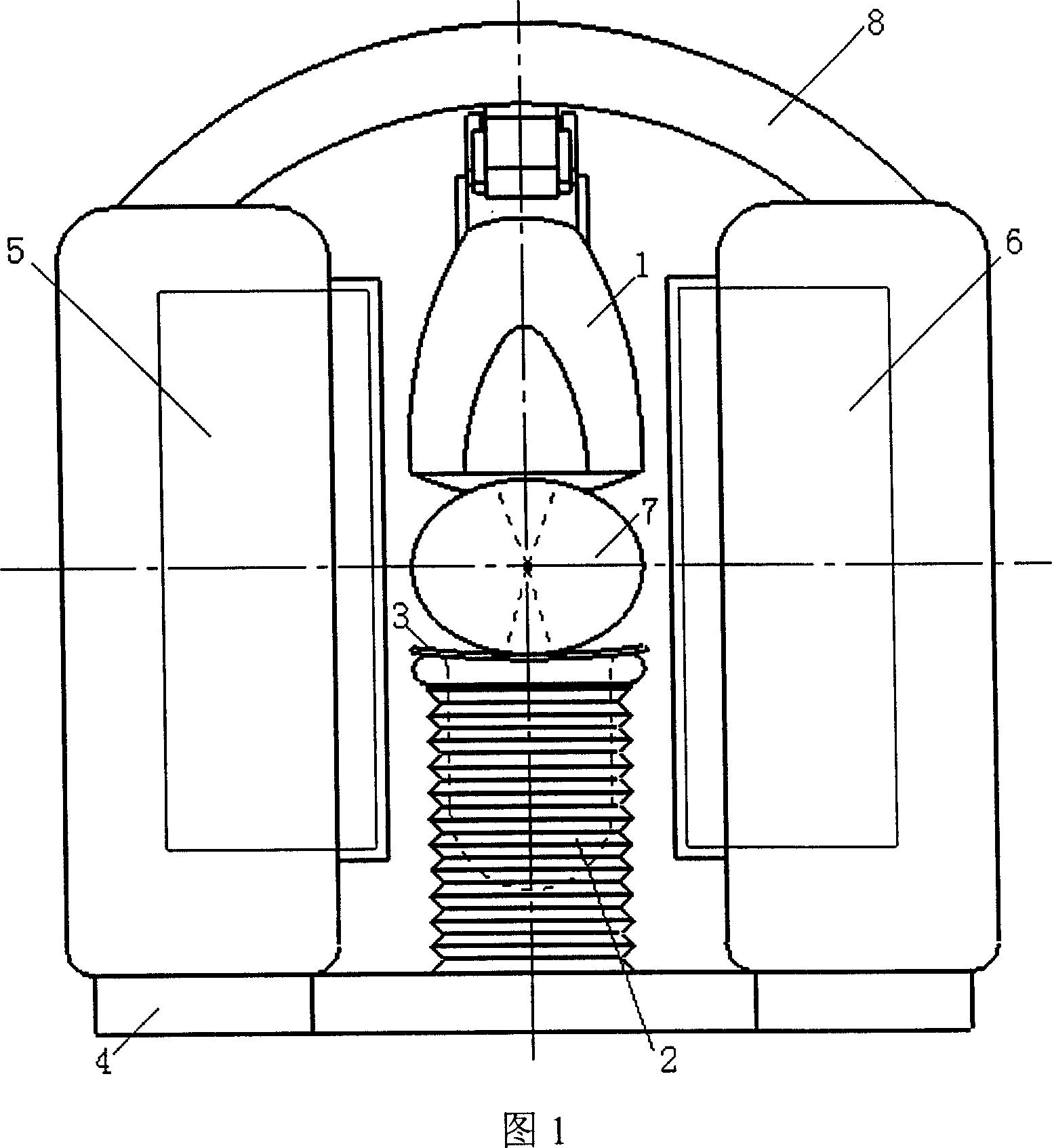
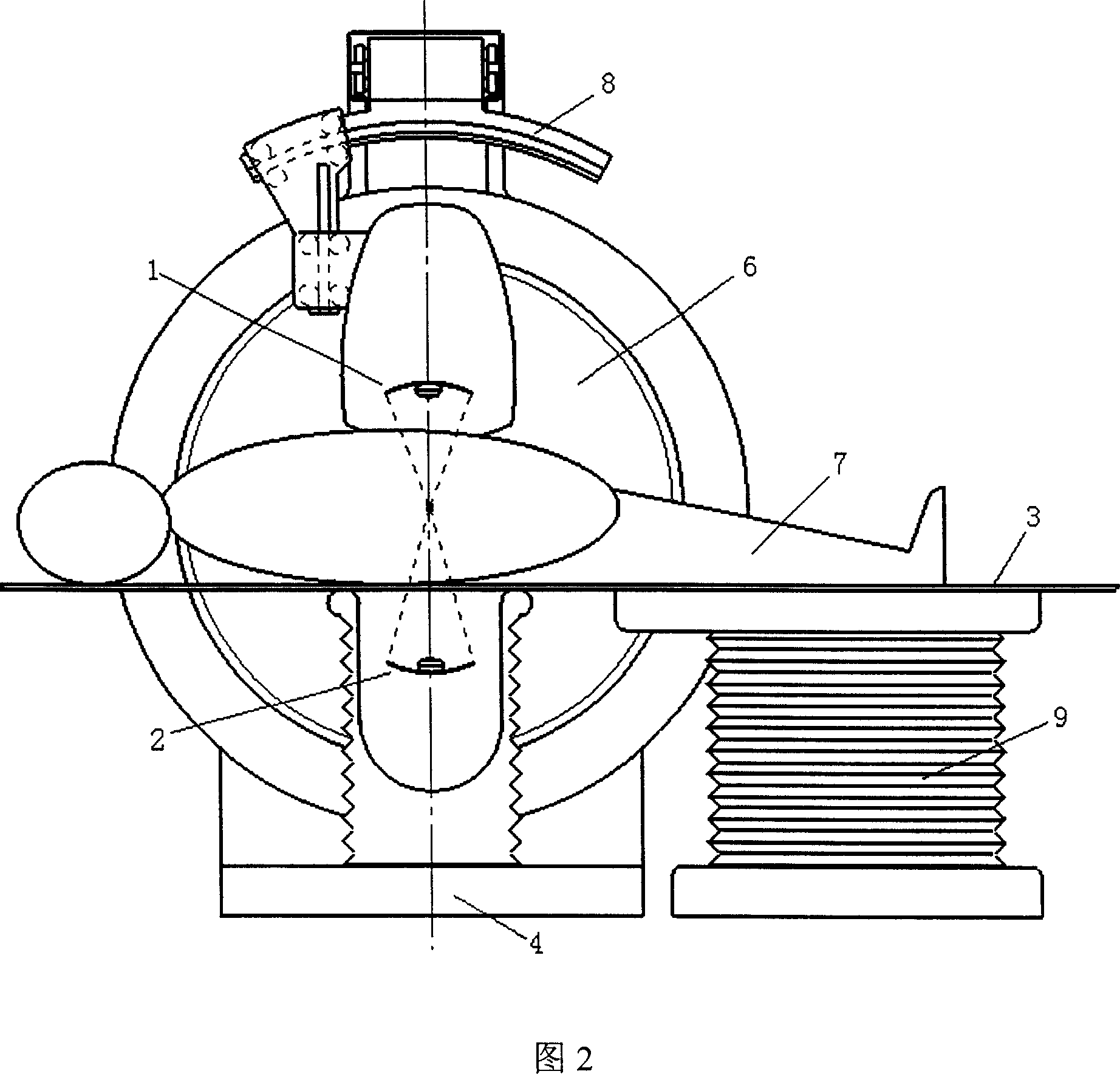
[0024] As shown in Figure 1-2, a HIFU tumor ablation system includes an open MRI system, the magnetic materials 5 and 6 of the open MRI system are arranged perpendicular to the ground, and the direction of the main constant magnetic field of the MRI system is parallel to the ground , also includes an upper-mounted HIFU treatment device 1 arranged on the upper part between the magnetic materials of the open MRI system and a lower-mounted HIFU treatment device 2 arranged on the lower part between the magnetic materials of the open MRI system, and also includes a Patient support device 3 for carrying a patient.
[0025] The magnetic materials 5 and 6 are vertically arranged on a base 4 placed horizontally on the ground. The MRI magnetic resonance imaging system adopts an open structure with its opening facing upwards. The HIFU high-intensity focused ultrasound system is placed at the opening of the MRI magnetic resonance imaging system.
[0026] Wherein, the top-mounted HIFU trea...
Embodiment 2
[0032] Embodiment 2 differs from Embodiment 1 in that: the HIFU treatment device is an upper-mounted HIFU treatment device located above the patient carrying device, not shown in the figure, and the other structures of Embodiment 2 are the same as those of Embodiment 1, and are not mentioned here. Do repeat.
Embodiment 3
[0034] Embodiment 3 differs from Embodiment 1 in that: the HIFU treatment device is a lower-mounted HIFU treatment device located below the patient carrying device, which is not shown in the figure. The other structures of Embodiment 3 are the same as those of Embodiment 1, and are not mentioned here. Do repeat.
PUM
 Abstract
Description
Claims
Application Information