Welding jig for welding cylinder

A technology for assembling welding jigs and cylinders, applied in the field of assembling and welding jigs, can solve problems such as affecting welding efficiency, and achieve the effects of reliable and convenient clamping, high efficiency, and accurate circumferential tightening.

Inactive Publication Date: 2007-05-23
HUAZHONG UNIV OF SCI & TECH
View PDF0 Cites 16 Cited by
  • Summary
  • Abstract
  • Description
  • Claims
  • Application Information

AI Technical Summary

Problems solved by technology

In addition, the assembly point fixing and welding of the existing welding methods are often

Method used


Image

  • Welding jig for welding cylinder
  • Welding jig for welding cylinder
  • Welding jig for welding cylinder

Examples


Example Embodiment

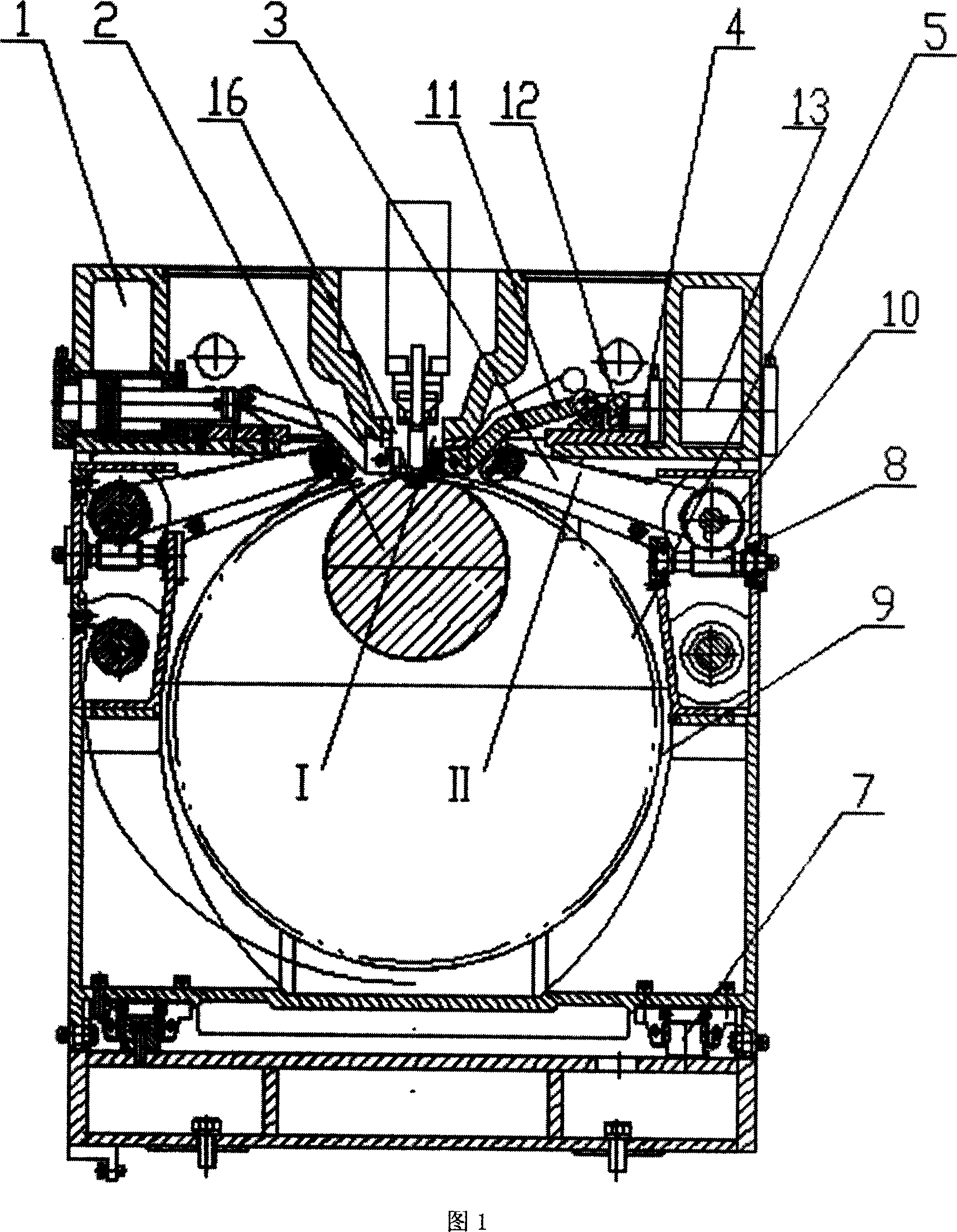
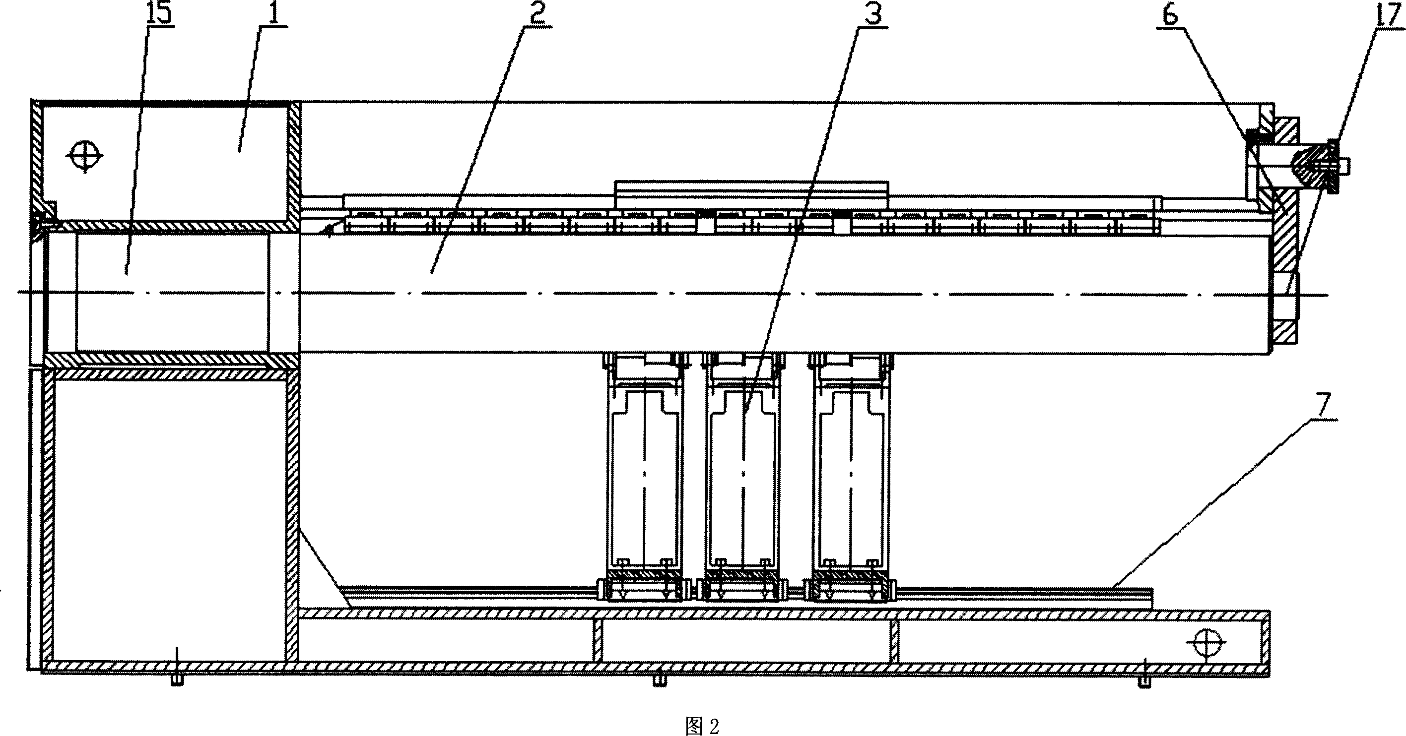
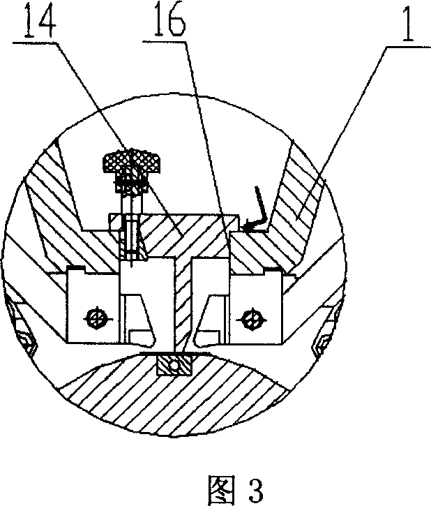
[0017] Fig. 1 is a structural schematic diagram of a welding jig for a welding cylinder of the present invention, and Fig. 2 is a left view of Fig. 1 . As shown in the figure, 1 is the frame, 2 is the mandrel, 3 is the steel belt tightening device, 4 is the clamping device, 5 is the workpiece, the positioning hole 15 is opened on one side of the frame 1, and one end of the mandrel 2 Installed in the positioning hole 15 of the frame 1, the other end of the mandrel 2 is installed in the positioning hole 17 of the pin plate 6, the inert gas can pass through the mandrel 2, and is used for welding that needs to be protected on the back of the workpiece, and the pin plate 6 is hung On one side of the frame 1, and can be disassembled when clamping the workpiece, the guide rail 7 is installed on the bottom of the frame 1, the steel belt tightening device 3 is installed on the guide rail 7, and can slide along the guide rail 7 for adjustment and tightening The number of steel belt tigh...


PUM

PropertyMeasurementUnit
Thicknessaaaaaaaaaa

Abstract

The invention relates to a welding clamper which uses steel band to pack, with installment space reduction function, and longitudinally weld the coiled plate into cylinder, wherein said clamper comprises that: frame, spindle, positioning block for welding and positioning sheet which will be detached when the steel band is positioned; the steel band coiling device is mounted on the track of clamper, formed by steel band, worm device, and tension wheel; said steel band can be coiled to move longitudinally, to apply different work pieces; the clamper is formed by compressing plate, wedge block and cylinder, to clamp two opens of cylinder on the spindle. The invention has high efficiency and accuracy position.

Description

technical field [0001] The invention relates to a welding jig for welding into a cylinder, in particular to a welding jig for welding a rolled plate into a cylinder longitudinally by wrapping it with a steel band. Background technique [0002] In petrochemical, military and other fields, cylindrical parts such as pipelines and missile shells are often welded by plates. Welding plates into cylinders is an important process in the manufacture of such parts. The existing processing method is generally to roll the plate into an open cylinder by a plate rolling machine, then manually gather the open cylinder and use the spot welding section to form a preliminary shape, and then use a welding machine to perform laser or argon arc welding along the longitudinal direction to obtain the cylindrical part . [0003] When adopting the existing welding method, the jig for manually closing the open cylinder has no mechanical positioning and closing movement in the circumferential direct...

Claims


Application Information

Patent Timeline
IPC IPC(8): B23K37/053B23K26/20B21C37/08B23K26/70
Inventor 段正澄鲍剑斌胡伦骥黄禹阮海洪邓家科李斌胡家强
Owner HUAZHONG UNIV OF SCI & TECH
Why Eureka
Try Eureka