

Method for producing optical fiber probe
An optical fiber probe and optical fiber technology, which is applied in the directions of light guides, optics, optical components, etc., can solve the problems of high price and difficulty in ensuring the consistency and repeatability of optical fiber probes, and achieve the effect of low cost, convenient operation and easy mass production.
- Summary
- Abstract
- Description
- Claims
- Application Information
AI Technical Summary
Problems solved by technology
Method used
Image

Examples
Embodiment 1
[0033] Embodiment 1, the making of combined tapered optical fiber probe
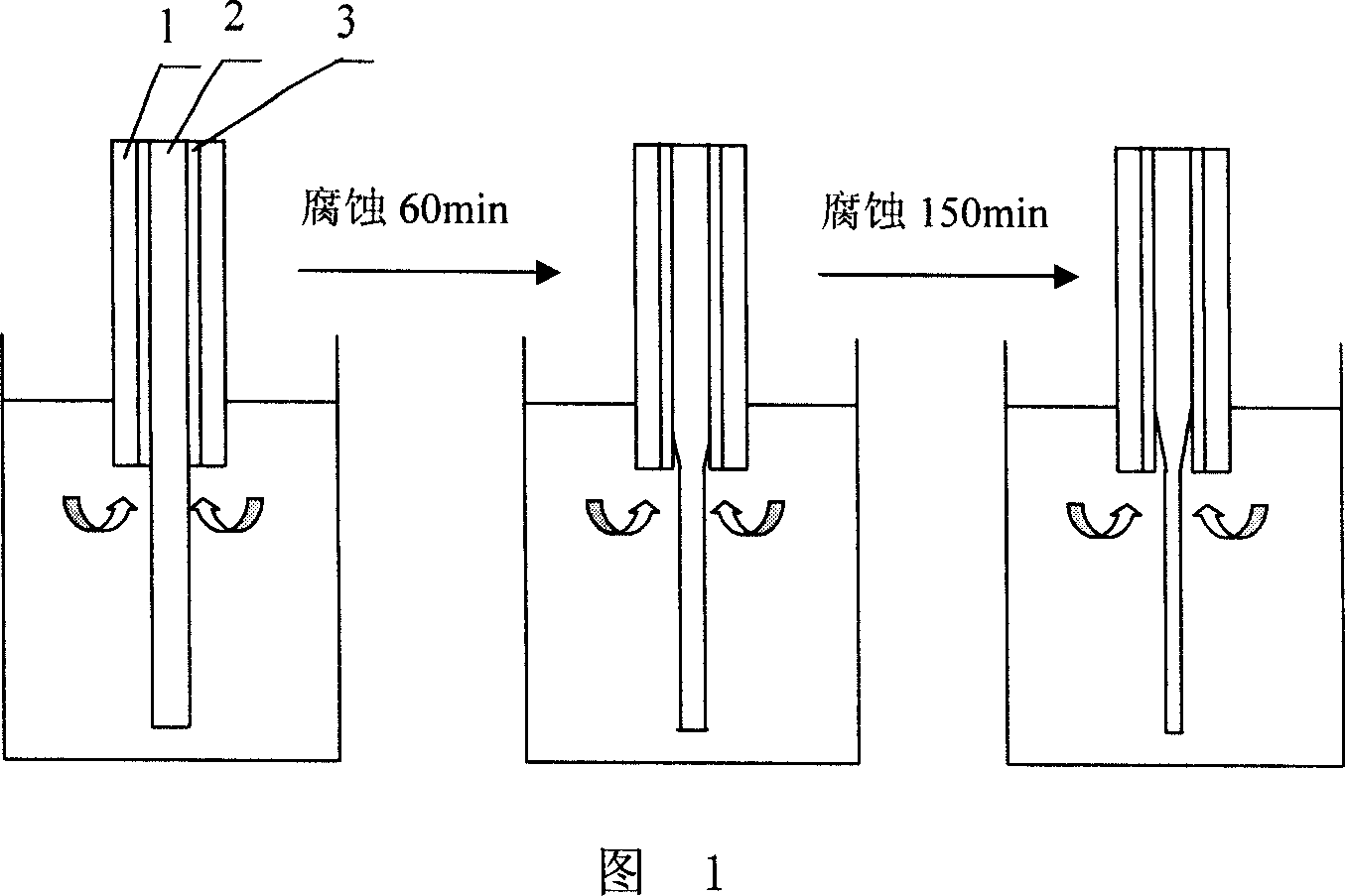
[0034] As shown in Figure 1, first cut the fiber with a core diameter of 600 μm and a cladding thickness of 10 μm (Nanjing Chunhui Technology Industrial Co., Ltd.) into 11 cm long fiber segments with a special fiber cutter, and then grind one end of the fiber with fiber grinding equipment Flat and polished with a polisher. From the unpolished end of the fiber segment, remove the plastic sheath 1 on the surface of the fiber by 6.3 cm with special pliers, and finally remove the coating 3 of this part carefully with a blade to expose the core and the cladding of the cladding 2.
[0035] Insert the part of the above-mentioned treated optical fiber section with the removed plastic sheath 1 and coating 3 facing down into the solution filled with hydrofluoric acid (the mass percent concentration of HF is 30%), the immersion depth is 7.3cm, and the corrosion time 180min. The tapered optical fiber probe shown i...
Embodiment 2
[0037]Embodiment 2, the making of combined tapered optical fiber probe
[0038] As shown in Figure 1, first cut the fiber with a core diameter of 600 μm and a cladding thickness of 10 μm (Nanjing Chunhui Technology Industrial Co., Ltd.) into 11 cm long fiber segments with a special fiber cutter, and then grind one end of the fiber with fiber grinding equipment Flat and polished with a polisher. From the unpolished end of the fiber segment, remove the plastic sheath 1 on the surface of the fiber by 6.3 cm with special pliers, and finally remove the coating 3 of this part carefully with a blade to expose the core and the cladding of the cladding 2.
[0039] Insert the part of the above-mentioned processed optical fiber section with the plastic sheath 1 and coating 3 removed downwards into a solution containing hydrofluoric acid (the mass percentage concentration of HF is 20%), and the immersion depth is 7.3 cm, and the corrosion time is 7.3 cm. It is 240min. A tapered optical ...
Embodiment 3
[0041] Embodiment 3, the making of combined tapered optical fiber probe
[0042] As shown in Figure 1, first cut the fiber with a core diameter of 600 μm and a cladding thickness of 10 μm (Nanjing Chunhui Technology Industrial Co., Ltd.) into 11 cm long fiber segments with a special fiber cutter, and then grind one end of the fiber with fiber grinding equipment Flat and polished with a polisher. From the unpolished end of the fiber segment, remove the plastic sheath 1 on the surface of the fiber by 6.3 cm with special pliers, and finally remove the coating 3 of this part carefully with a blade to expose the core and the cladding of the cladding 2.
[0043] Insert the part of the above-mentioned processed optical fiber section with the plastic sheath 1 and the coating 3 removed downwards into the solution containing hydrofluoric acid (the mass percent concentration of HF is 10%), and the immersion depth is 7.3cm, and the corrosion time It is 360min. A tapered optical fiber pr...
PUM
| Property | Measurement | Unit |
|---|---|---|
| diameter | aaaaa | aaaaa |
| length | aaaaa | aaaaa |
| diameter | aaaaa | aaaaa |
Abstract
Description
Claims
Application Information