Clock recovery method and apparatus

A clock recovery and clock signal technology, applied in the field of network communication, can solve the problems of limited operation speed of digital signal processor, increase of system complexity and cost, bandwidth limitation of system phase-locked loop, etc., to achieve improved jitter performance, low jitter, etc. The effect of output, high realization cost

Active Publication Date: 2007-05-23
HUAWEI TECH CO LTD
View PDF0 Cites 15 Cited by
  • Summary
  • Abstract
  • Description
  • Claims
  • Application Information

AI Technical Summary

Problems solved by technology

[0012] However, due to the limited operation speed of the existing digital signal processor, the sampling rate and order of the digital filter are limited, which limits the bandwidth of the system phase-locked loop; at the same time, the external digital signal processor, digital-to-analog conversion controller will add complexity and cost to the system
[0013] Therefore, the existing demapping processing implementation scheme, due to the defects in the clock recovery design, makes the phase detection clock or phase detection pulse output by it still contain a large non-uniform gap time slot, or makes the entire phase locked loop Bandwidth too low

Method used


Image

  • Clock recovery method and apparatus
  • Clock recovery method and apparatus
  • Clock recovery method and apparatus

Examples


Embodiment 1

[0060] Embodiment 1: A clock recovery scheme in which the digital filter is placed outside the phase-locked loop

[0061] This solution is preferably but not limited to be implemented inside the demapping processing chip.

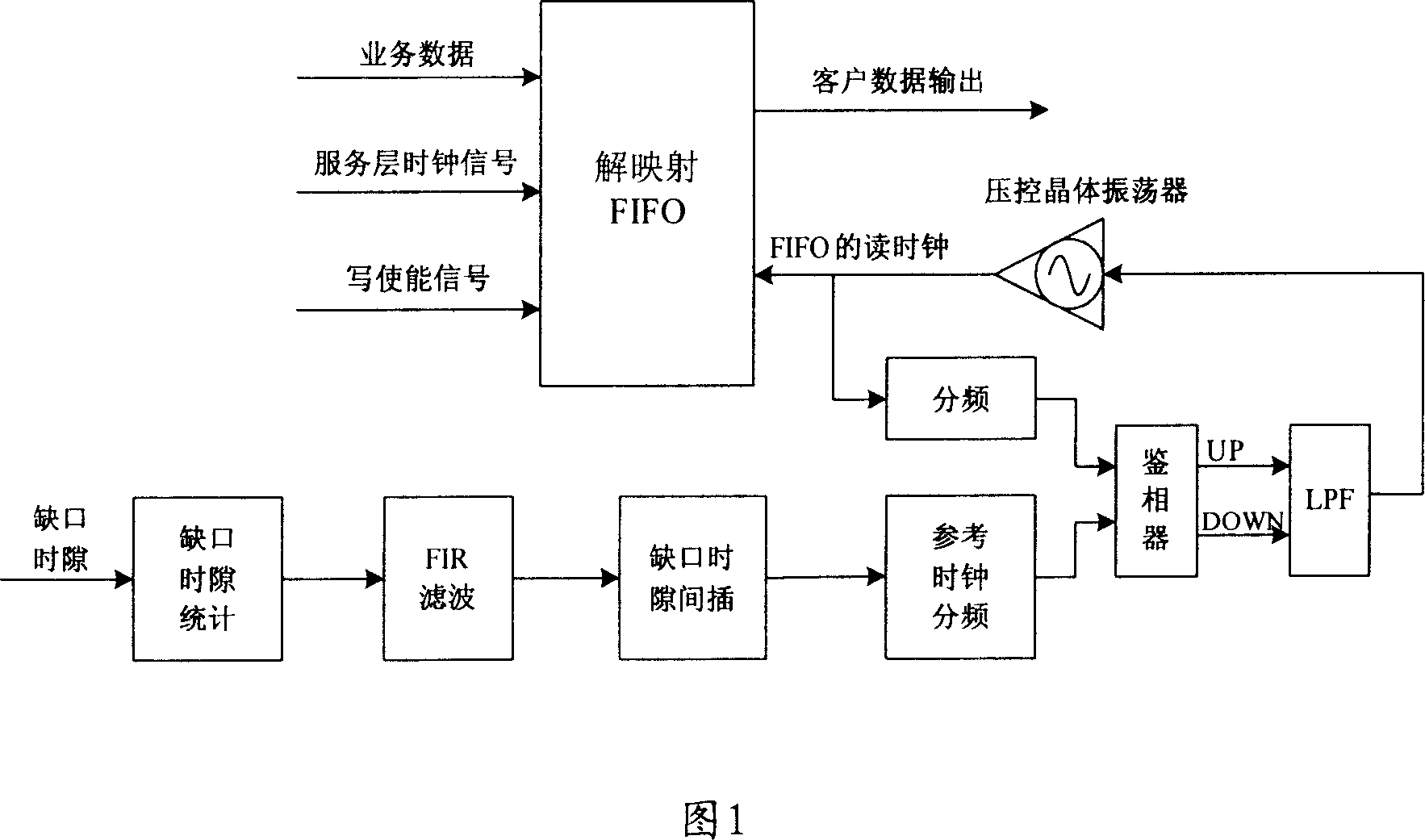
[0062] In this implementation scheme, a demapping circuit with excellent performance can be formed by specifically adopting a digital filter, an external low-pass filter (LPF) and a voltage-controlled crystal oscillator. The digital filter can use FIR (finite length Unit Impulse Response) filter, the corresponding specific implementation circuit structure is shown in Figure 1, in which the FIR filter is used as an example, but the actual application is not limited to the FIR filter.

[0063] As shown in Figure 1, the usual business data processing flow in the corresponding demapping process includes:

[0064] When the signal time slot of the client layer is valid, the write enable signal of the demapping FIFO is valid, so that the customer data can be writ...

Embodiment 2

[0084] Embodiment 2: A clock recovery scheme in which a digital filter is placed inside a phase-locked loop

[0085] For applications where the loop bandwidth is not required, the digital filter can also be placed inside the clock phase-locked loop. The specific implementation structure of the implementation scheme provided by this embodiment is shown in Figure 4, including:

[0086] Write data statistics unit, read data statistics unit, take difference unit and digital filtering unit, wherein, the output of data statistics unit and read data statistics unit are respectively used as the input of difference take unit, and the output of take difference unit is connected to all The above-mentioned digital filter unit, and the digital filter unit is connected with the phase-detection pulse conversion unit of the phase-locked loop.

[0087] The specific implementation of each processing unit included in FIG. 4 will be described respectively below:

[0088] (1) Read data statistic...

Embodiment 3

[0101] Embodiment 3: A solution for improving the jitter performance of the demapping clock by using a digital filter


PUM


Abstract

The invention relates to a method for recovering clock and relative device, wherein it uses digit filter with full hardware logic in de-projection clock recover circuit; it uses point method to make FIR filter smoothly output cut time slit; it uses analogue phase-lock loop to recover the client clock, improves the vibration property when recovers clock. The invention can recover clock with low vibration, to improve bandwidth and stability of whole phase-lock loop, with low cost.

Description

technical field [0001] The invention relates to the technical field of network communication, in particular to a method and device for realizing clock recovery which improves and enhances clock recovery performance. Background technique [0002] In the telecommunication network, in order to effectively utilize the bandwidth of the transmission medium, the low-speed client layer signal is usually mapped to the high-speed service layer signal by multiplexing at the source end, and then transmitted to the sink end through the transmission medium; at the sink end When the terminal is demultiplexed, it is necessary to use a special circuit to recover the clock of the client layer signal. Wherein, the mapping specifically includes: synchronous mapping and asynchronous mapping. [0003] The synchronous mapping requires that there must be a fixed ratio between the signal rate of the client layer and the signal rate of the server layer. When demapping, the signal clock of the server...

Claims


Application Information

Patent Timeline
Patent Type & Authority Applications(China)
IPC IPC(8): H04J3/06
Inventor 吴继东
Owner HUAWEI TECH CO LTD
Why Eureka
Try Eureka