Bionic rotary-cutting and stubble-breaking blade

A technology of blade and stubble, applied in application, tillage equipment, crop processor, etc., can solve problems such as low operation efficiency, and achieve the effect of low soil cutting resistance, easy popularization and application, and excellent performance.

Inactive Publication Date: 2007-05-30
JILIN UNIV
View PDF0 Cites 12 Cited by
  • Summary
  • Abstract
  • Description
  • Claims
  • Application Information

AI Technical Summary

Problems solved by technology

If two operations of rotary tillage and stubble breaking are to be realized, the knife stick and the corresponding blades must be replaced with the existing blades. This operation is not only time-consuming, but also the operation efficiency is relatively low.

Method used


Image

  • Bionic rotary-cutting and stubble-breaking blade
  • Bionic rotary-cutting and stubble-breaking blade
  • Bionic rotary-cutting and stubble-breaking blade

Examples


Embodiment Construction

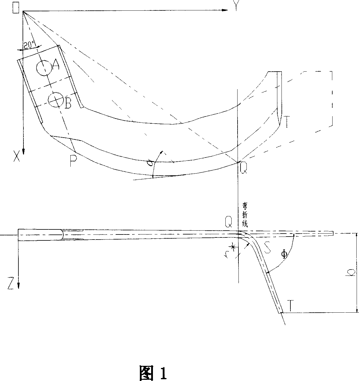
[0013] Fig. 1 shows the structure of the general blade of the bionic rotary tillage of the present invention. In Fig. 1, the coordinate origin O is the intersection point of the side section of the blade and the center line Z of the cutter roller axis, and the upper part of Fig. 1 represents the general blade Schematic diagram of the structure in the XYZ coordinate system, wherein the dotted line part is the projection of the tangent surface of the universal blade in the XOY plane, and the lower part of Fig. 1 represents the projection of the universal blade in the YOZ plane. In the XYZ Cartesian coordinate system, the Z axis is the center line of the cutter roller axis, the side cut surface is in the XOY plane, but the tangent surface is not in the XOY plane, and it bends toward the Z axis along the bending line, as shown in the lower part of Figure 1 . The transition face (where the QS surface is located) is located between the side cut face and the tangent face. The two po...


PUM


Abstract

The invention discloses a bionic rotary tillage stubble-grinding general-purpose blade, which is composed of lateral tangent plane part, positive tangent plane part and transition part between lateral and positive tangent plane parts, wherein the positive and lateral tangent plane parts aren't in the same plane; the positive tangent plane bends along bending line of knife shaft.

Description

technical field [0001] The invention belongs to the field of agricultural machinery, in particular to a rotary tillage blade. Background technique [0002] Rotary tillage and stubble breaking are the two most common soil cultivation methods in China (especially in the north). Full-width rotary tillage is generally used for flat farming, such as paddy fields, vegetable fields, wheat fields, etc., and stubble is generally used for ridge farming in the north. There are many rotary tillers in foreign countries, but there is no separate stubble breaker. On some no-tillage seeders, stubble removal parts are installed in front of the seeder ditch opener to remove the stubble in the crop row. Domestic rotary tillage or stubble crushing operations have more than tens of thousands of single machines. In recent years, there have been some models that can complete two operations of rotary tillage and stubble crushing on one machine tool. There are two main types: (1) replace different...

Claims


Application Information

Patent Timeline
Patent Type & Authority Applications(China)
IPC IPC(8): A01B33/10A01D82/00
Inventor 贾洪雷黄东岩马成林王增辉谭宏杰李春胜李广宇刘昭辰
Owner JILIN UNIV
Why Eureka
Try Eureka