
Drive pulleys

A technology for driving pulleys and pulleys, applied in electric components, engine components, machines/engines, etc., can solve the problems of low overall work efficiency, waste of energy by cooling pumps, etc., and achieve the effect of low cost

Inactive Publication Date: 2007-05-30
NEXXTDRIVE LTD
View PDF0 Cites 5 Cited by
  • Summary
  • Abstract
  • Description
  • Claims
  • Application Information

AI Technical Summary

Problems solved by technology

Furthermore, as a result of the fact that the cooling pump can consume around 10% of the engine's total output power, this means that for most of the engine's operating time, the cooling pump is wasting energy, which in turn means that the overall operating efficiency of the engine is less than theoretical Achievable value

Method used


Image

  • Drive pulleys
  • Drive pulleys

Examples


Embodiment Construction

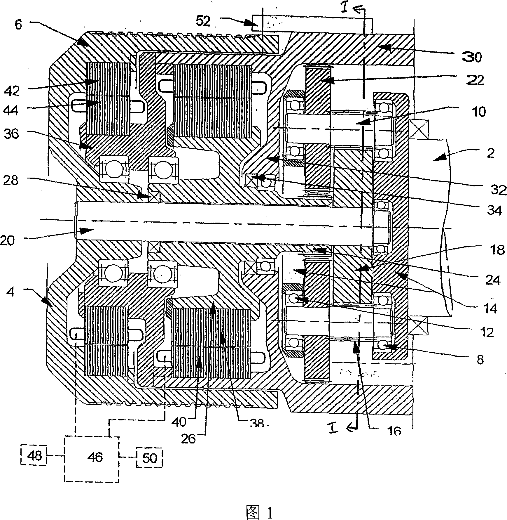
[0021] The pulley shown in the drawing is shown connected to the crankshaft 2 of the engine. The crankshaft 2 is connected to the input of a transmission system comprising a planetary gear set, the output of which is connected to a generally cup-shaped hollow cylindrical member 4 having a plurality of V-shaped grooves on its outer surface of circular cross-section, And constitute the belt mating surface 6 of the multi-V pulley.

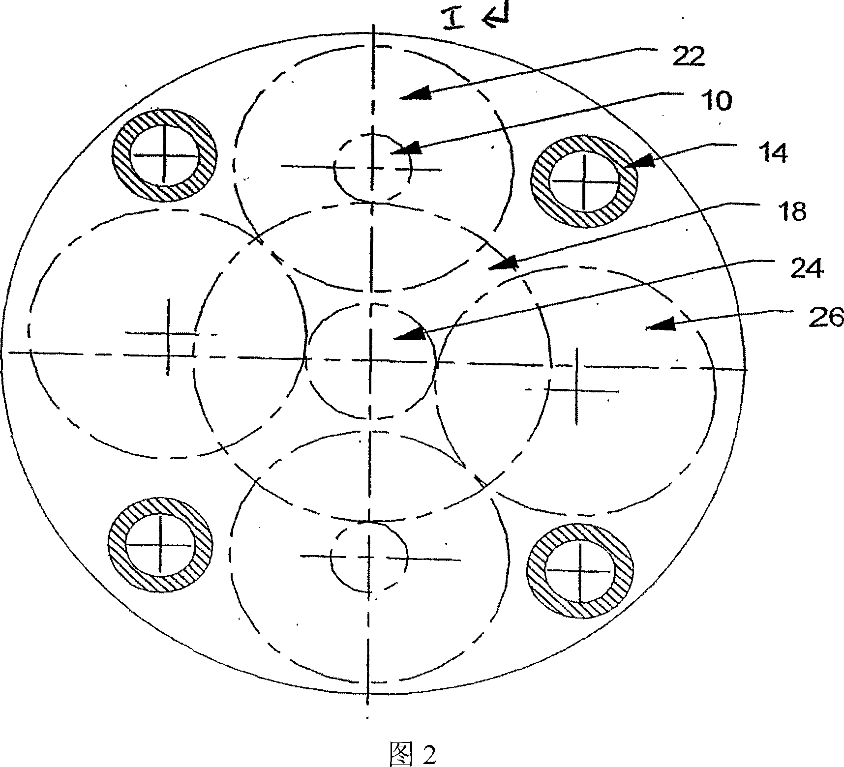
[0022] More specifically, the input consists of two ball bearings 8 supported by annular rings and connected together. The ball bearings 8 accommodate one end of a respective planetary shaft 10 of the planetary gearset, the other end of which is accommodated in a respective further ball bearing 12 . The two ball bearings 12 are supported and connected together by another annular ring. The two annular rings are connected together by four posts, which are only visible in Figure 2. The two annular rings and the four posts together form the carrier 14 ...


PUM


Abstract

A drive pulley for a cooling pump or the like of an .engine includes an input (14) for connection to the engine and an output comprising a hollow cylindrical member (4), whose outer surface (6) constitutes a pulley belt engagement surface. The input and output are connected by a transmission system comprising an epicyclic gearset including two or more first planet gears (16), which are connected to respective planet shafts (10) to rotate about the axis thereof and are in mesh with a first sun gear (18). The gearset also includes two or more second planet gears (22), which are connected to rotate with respective first planet gears (16) and are in mesh with a second sun gear (24). The planet shafts (10) are connected to a common carrier (14) which constitutes the input. The first sun gear (18) is connected to the output (4). The transmission system further includes two electric motor / generators (38, 40; 42, 44), the rotors (38, 42) of which are connected to the second sun gear (24) and the output(4), respectively, and the electrical stator connections of which are connected to a controller (46) arranged selectively to control the flow of electrical power between them. The transmission system is at least partially accommodated within the hollow cylindrical member (4).

Description

technical field [0001] The invention relates to a drive pulley for connecting an engine, especially an automobile engine, to drive auxiliary equipment such as a coolant pump or a cooling fan, the coolant pump circulates the coolant in the cooling circuit, the cooling fan blows air to and / or blow through radiators or compressors, such as air conditioner compressors. Background technique [0002] Internal combustion engines typically include a coolant pump and / or a cooling fan (collectively referred to herein as a "cooling pump") to dissipate excess heat from the engine and prevent the engine from overheating. Such cooling pumps typically have an input shaft with a pulley that is driven by a drive belt that also passes around a drive pulley that is mounted directly on one end of the engine crankshaft or on a shaft driven by the crankshaft. Therefore, the speed of the drive pulley is usually directly related to the speed of the engine. [0003] However, internal combustion en...

Claims


Application Information

Patent Timeline
IPC IPC(8): F01P5/12F04D13/02F02B39/06H02K7/10H02K7/116H02K16/00
CPCF04D13/021F01P5/12H02K7/1016H02K7/116H02K16/00F04D13/028F04D13/02F02B39/06
Inventor F·莫埃列尔
Owner NEXXTDRIVE LTD
Learn More