
Eureka
For R&D, Eureka makes reading and utilizing patents & technical documents easy.
Eureka AIR
Designed for self-driven R&D workflows. Generate viable solutions, solve complex R&D challenges, empower your innovation with AI.

Eureka Materials
Designed for material experts only. Revolutionize your material R&D, from search, analyze, to developing new materials.

TechResearch
Generate reliable direction feasibility study reports for your R&D in just a few steps.

TechSeek
Discover and master advanced knowledge NOW. Basics, ideas, possibilities, all at once.

TechMind
As an expert in R&D Theories, TechMind can generates customized viable solutions instantly.

TechRisk
Analyze your overall solution with one click, know your potential R&D risks in advance.

TechMonitor
Get weekly tech updates, stay abreast of the latest tech innovations and key insights.
Computerized method of remote monitoring temperature of aluminium electrobath casing
An aluminum electrolytic cell and remote monitoring technology, which is applied in the field of monitoring the temperature of the aluminum electrolytic cell shell, can solve problems such as error-prone and failure to detect hidden dangers in time, and achieve the effect of ensuring normal operation, avoiding further deterioration of the cell condition or even stopping the cell
- Summary
- Abstract
- Description
- Claims
- Application Information
AI Technical Summary
Problems solved by technology
Method used
Image

Examples
specific Embodiment approach 1
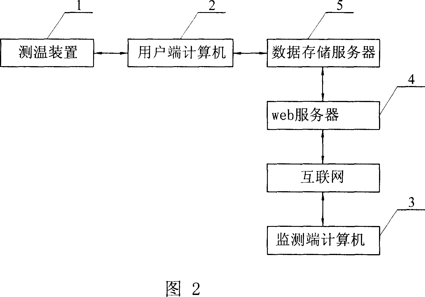
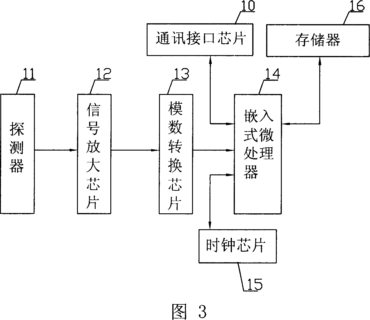
[0022] Specific embodiment 1: As shown in Figure 2, a method of using a computer to remotely monitor the temperature of the aluminum electrolytic cell shell in this specific embodiment is to use a temperature measuring device 1, a user end computer 2, and a monitoring end computer connected to the network 3, web server 4 and the data storage server 5 that is arranged between client computer 2 and web server 4 realize; As shown in Figure 3, described temperature measuring device 1 is provided with the detector 11 that object temperature is measured , signal amplification chip 12, analog-to-digital conversion chip 13, embedded microprocessor 14, clock chip 15, memory 16 and the communication interface chip 10 that is connected with client computer 2, the output terminal of detector 11 connects the input of signal amplification chip 12 end, the output end of the signal amplification chip 12 is connected to the input end of the analog-to-digital conversion chip 13, and the output e...
specific Embodiment approach 2
[0055] Specific embodiment two: as shown in Figure 7, the data monitoring in the monitoring method described in this embodiment includes the temperature monitoring of the measuring surface, which is carried out in the following steps:
[0056] 1. Use the temperature measuring device 1 to measure the temperature of the preset measuring points on each side of the electrolytic tank, and then save the temperature data together with the measuring time (accurate to minutes), the number of the measuring point and the information of the measuring tank number in the memory of the temperature measuring device 1 16 in;
[0057] 2. The client computer 2 reads the data in the temperature measuring gun and saves it in the database;
[0058] 3. The monitoring end users access and analyze the database data through the browser, the specific steps are:
[0059] 3-1. Monitor the user to open the browser, enter the website name in the address bar or enter the operating parameters on the page;
...
PUM
 Abstract
Description
Claims
Application Information
 - R&D Engineer
- R&D Manager
- IP Professional
- Industry Leading Data Capabilities
- Powerful AI technology
- Patent DNA Extraction
Browse by: Latest US Patents, China's latest patents, Technical Efficacy Thesaurus, Application Domain, Technology Topic, Popular Technical Reports.
© 2024 PatSnap. All rights reserved.Legal|Privacy policy|Modern Slavery Act Transparency Statement|Sitemap|About US| Contact US: help@patsnap.com