Forced-air-cooled engine with cooling air guide cover

一种强制空冷、发动机的技术,应用在发动机元件、机器/发动机、发动机的冷却等方向,达到防止漏出的效果

Active Publication Date: 2007-06-06
MITSUBISHI HEAVY IND MEIKI ENGINES CO LTD
View PDF2 Cites 6 Cited by
  • Summary
  • Abstract
  • Description
  • Claims
  • Application Information

AI Technical Summary

Problems solved by technology

[0011] The problem is whether it is possible to obtain a part with an appropriate thickness in consideration of the elasticity and clamping amount of the above-mentioned support damper, and it is necessary to press the above-mentioned synthetic resin molded part on the cylinder block with a predetermined clamping amount. Front precise recess processing

Method used


Image

  • Forced-air-cooled engine with cooling air guide cover
  • Forced-air-cooled engine with cooling air guide cover
  • Forced-air-cooled engine with cooling air guide cover

Examples


Embodiment Construction

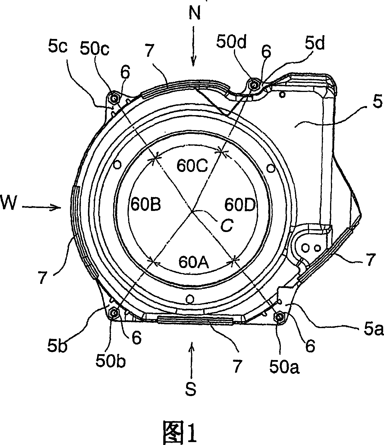
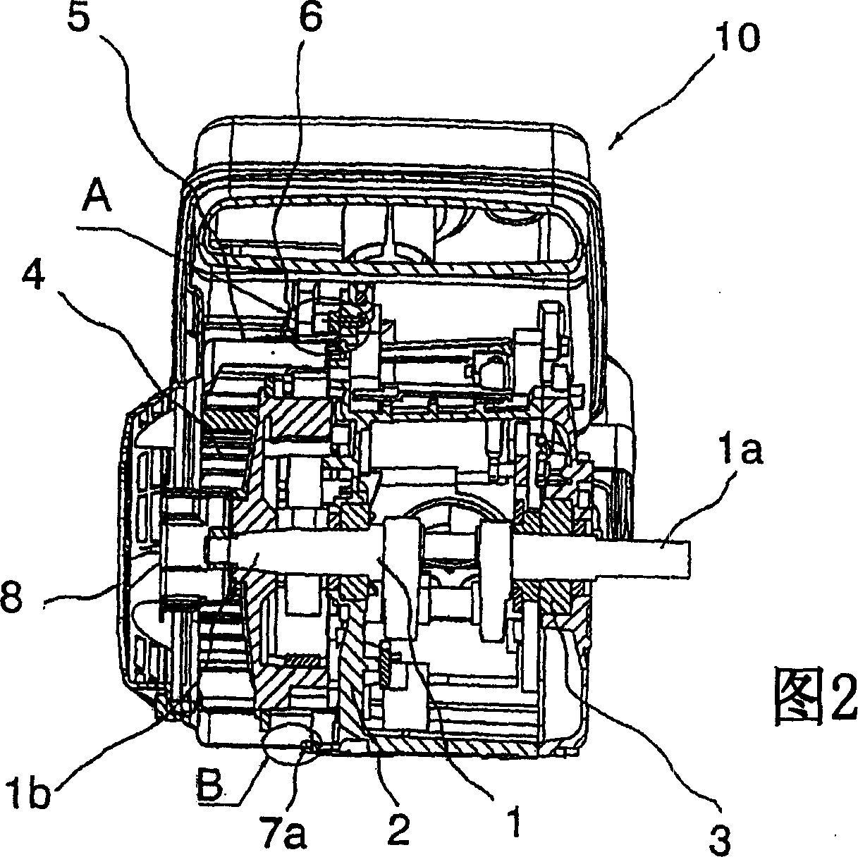
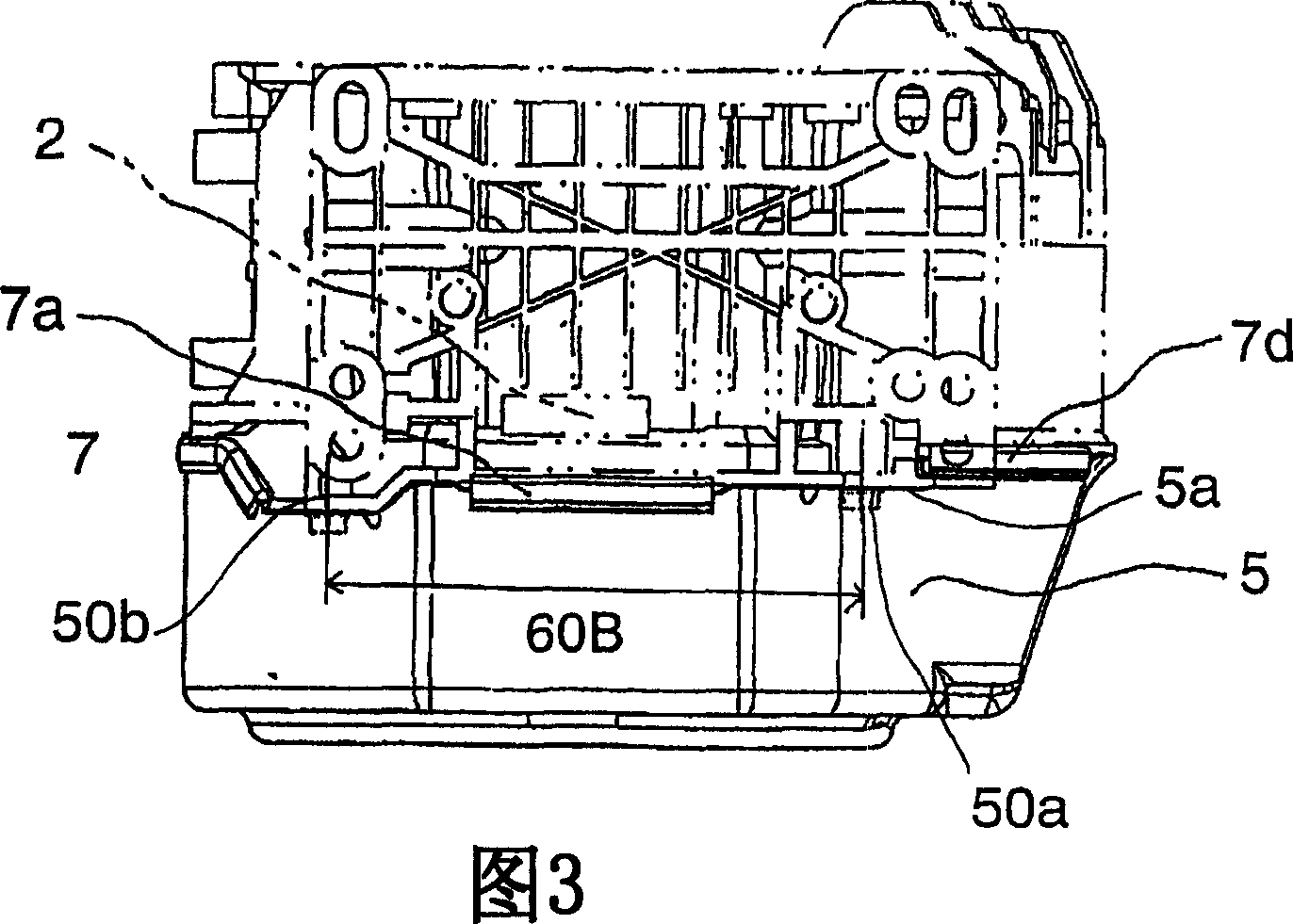
[0040] Embodiments of the present invention will be described with reference to the drawings. FIG. 1 is a front view of a cooling fan cover in a state where a soft vibration-proof member is embedded in a forced air-cooled engine, showing the inner surface of the fan cover viewed from the cylinder block side. Fig. 2 is a side sectional view of a forced air-cooled engine, including detailed parts and showing a cooling fan cover to which the present invention is applied in thick solid lines. Fig. 3 is a bottom view of the cooling fan cover of Fig. 1 seen from the S direction. FIG. 4 is also a side view of the cooling fan cover viewed from the N direction. FIG. 5 is also a side view of the cooling fan cover viewed from the W direction.

[0041] FIG. 6 is a vibration model showing a component of the cooling fan cover to facilitate understanding of the mode of resonance between the cooling fan cover and the engine to which the present invention is not applied. FIG. 7 shows a vibr...


PUM


Abstract

The invention provides a method and construction of vibration control supporting a cooling fan cover. In a forcer-air-cooled engine having a cooling fan cover fixed directly by means of fixing bolts to the cylinder block at fixing foot parts provided at a peripheral border of the fan cover, band-like vibration damping members are disposed between the peripheral border of the fan cover and the cylinder block in each region of the peripheral border belonging to each sector part defined between two adjacent fixing points of two adjacent fixing foot parts among said plurality of fixing foot parts respectively so that each of said damping members is pressed against the cylinder block by each region of the peripheral border when the bolts are tightened, said band-like damper members are flexible damping members each of which is disposed in an essential part of loop of vibration of the periphery for preventing generation of noise due to vibration of the fan cover with the fixing points as nodes of vibration resonating to cylinder block vibration, and said band-like flexible vibration damping members are adjusted thereby to adjust elastic force and damping capacity of the damping members so that resonance of the fan cover occurs at a rotation speed of engine higher than normal rotation speed thereof.

Description

technical field [0001] The present invention relates to a forced air-cooled engine having a cylinder block that integrally constitutes a crankcase portion and a cylinder portion, and particularly relates to an invention that provides an anti-vibration structure and an anti-vibration method for a cooling fan cover formed toward the above-mentioned The casing of the fan that supplies the cooling air to the cylinder block. Background technique [0002] In the forced air-cooled engine to which the present invention is applied, a crankshaft is arranged horizontally through a pair of crankshaft bearings in the crankcase portion of the cylinder block, and a cooling fan is installed on the crankcase portion on one end side of the crankshaft (crankshaft reverse output end side). The cylinder can be cooled by rotating following the rotation of the crankshaft and blowing cold air from the fan to the cylinder extending in the radial direction from the crankshaft and the heat radiation f...

Claims


Application Information

Patent Timeline
Patent Type & Authority Applications(China)
IPC IPC(8): F01P11/00F16F15/04
CPCF02F7/0068F01P11/10F02F7/008F02F7/0073F02F7/007F01P11/12F02B77/13F01P5/06F02B63/00
Inventor 河内弘吉关向学丸田洋辅
Owner MITSUBISHI HEAVY IND MEIKI ENGINES CO LTD
Why Eureka
Try Eureka