Coal powder boiler straight-flow burner igniting device

A pulverized coal boiler and ignition device technology, which is applied in the direction of combustion ignition, burner, burner for burning powder fuel, etc., can solve the problem of waste of ignition fuel oil, etc., achieve obvious fuel saving effect, simple structure, and wide industrial application prospects Effect

Inactive Publication Date: 2007-06-06
侯桂林
View PDF0 Cites 5 Cited by
  • Summary
  • Abstract
  • Description
  • Claims
  • Application Information

AI Technical Summary

Problems solved by technology

[0003] In order to solve the serious problem of waste of fuel oil in the ignition of pulverized coal boilers in existing thermal power plants, the present invention provides a brand new ignition device, which is developed according to a brand new combustion theory - stepless combustion technology, and requires only a small investment when igniting The amount of oil can safely and reliably meet the needs of large boilers with a capacity of 50-1000Mn in thermal power plants

Method used


Image

  • Coal powder boiler straight-flow burner igniting device
  • Coal powder boiler straight-flow burner igniting device
  • Coal powder boiler straight-flow burner igniting device

Examples


Embodiment Construction

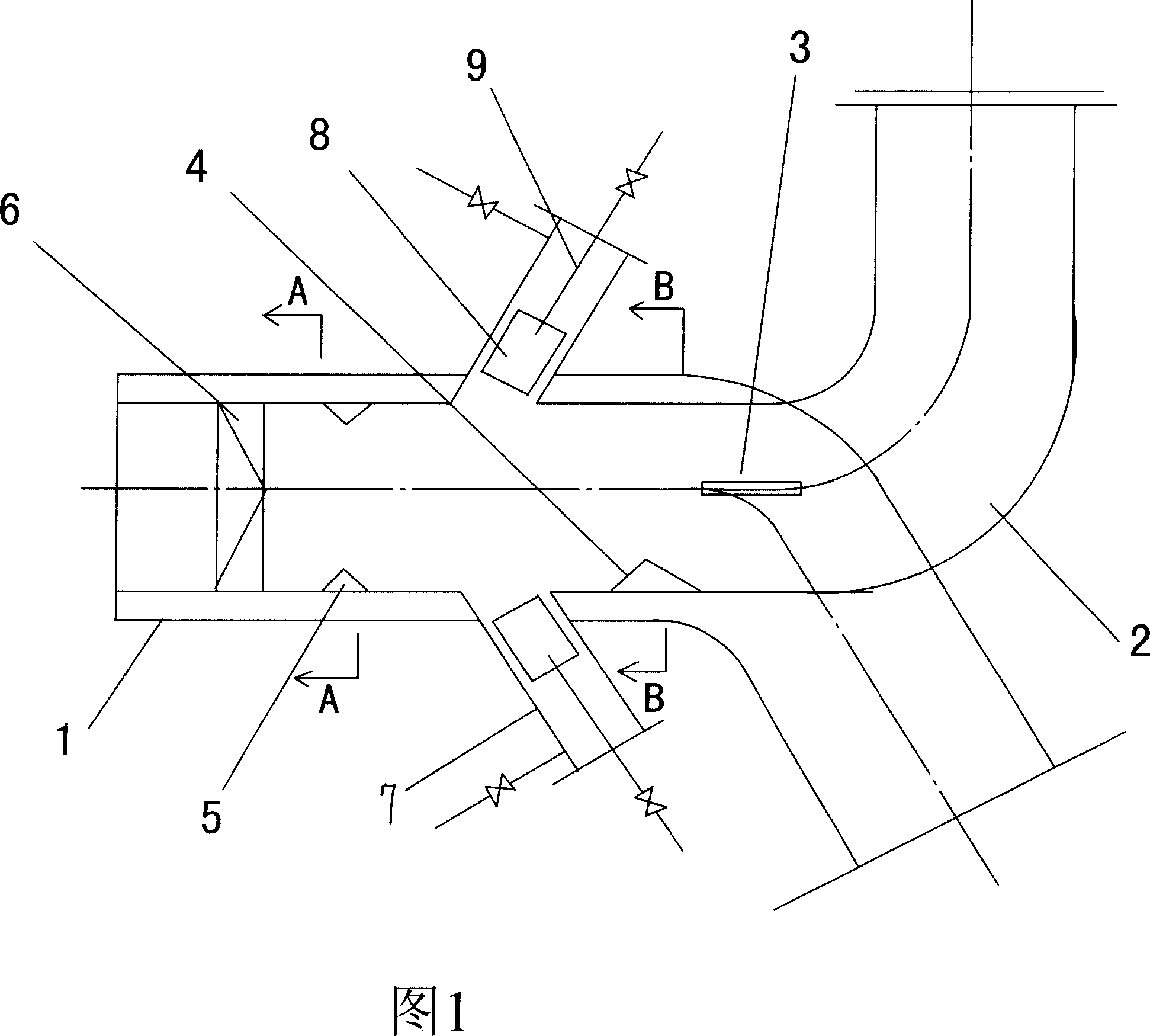
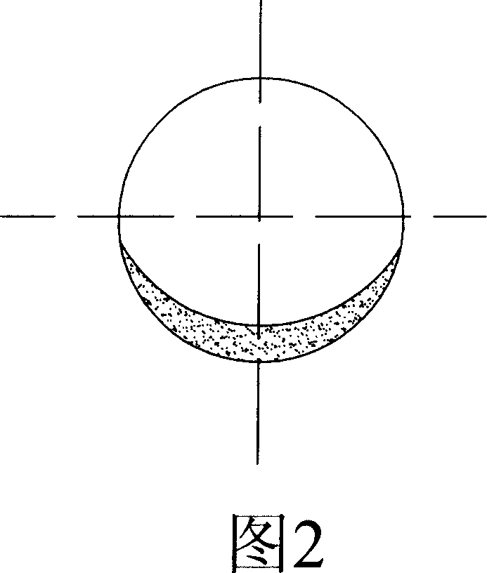
[0015] The ignition device of the direct current burner of the pulverized coal boiler includes the burner body 1 and the primary air pipe 2. The burner body 1 and the primary air pipe 2 are fixedly connected. Square opening. A separation partition 3 is welded in the primary air duct 2, and a crescent-shaped guide block 4 is welded on the front end of the separation partition 3 on the inner wall of the burner body 1, and three phases are welded on the inner wall of the front part of the burner body 1. The 120° stable combustion flap 5, the front part of the burner body 1 is fixed with a sky garden place 6, and the side wall of the burner body 1 is located between the guide block and the stable combustion flap 5. There are two mutually symmetrical and facing Rear inclined oil gun barrel 7, two oil gun barrels 7 are fixedly equipped with a combustion tube 8 respectively, and a small oil gun 9 is inserted in the combustion tube 8, and the small oil gun 9 inserts in the combustion ...


PUM


Abstract

The invention comprises a burner body and a primary flue pipe jointed firmly with the burner body. In the primary flue pipe is welded a separation plate. At the front end located on the inner wall of the burner body there is a guide block with a lug. On the inner wall of the burner front part are disposed several smooth burning pieces. On the side wall of the burner body located between the guide block and the smooth burning pieces are firm-jointed oil gun tubes having a combustion tube each. In each of combustion tubes is inserted a small oil gun.

Description

technical field [0001] The invention relates to an ignition device of a pulverized coal boiler in a thermal power plant, and is especially suitable for an ignition system of a direct-flow burner with injection combustion at four corners of the pulverized coal boiler. Background technique [0002] Existing large-scale pulverized coal boilers in thermal power plants need to burn a large amount of diesel oil during the process of starting and stopping the furnace to make the pulverized coal in the spray furnace burn. It is necessary to invest a large amount of diesel to support combustion in order to achieve the purpose of stable combustion. Therefore, the original ignition technology of thermal power plants has a large amount of fuel (the electric power industry consumes more than 12 million tons of fuel per year) and most of them are light diesel oil, which is a huge expenditure of production costs. Contents of the invention [0003] In order to solve the serious problem o...

Claims


Application Information

Patent Timeline
Patent Type & Authority Applications(China)
IPC IPC(8): F23C5/00F23D1/00F23Q9/00
Inventor 候桂林
Owner 侯桂林
Why Eureka
Try Eureka